ANTI-LOCK BRAKES
Anti-lock Brakes Wiring Diagram (1 of 2) for BMW 528i 1997

List of elements for Anti-lock Brakes Wiring Diagram (1 of 2) for BMW 528i 1997:
- Abs/asc control module (behind glove box)
- Auxiliary throttle position motor (ads)
- Brake light switch
- Can high
- Can low
- Computer data lines system
- Fuse f17 10a
- Fuse f30 25a
- Fuse f31 10a
- Fuse f8 25a
- Fuse panel 1
- Hot at all times
- Hot in run or start
- Instrument cluster
- Left front speed sensor (inside left front wheel hub)
- Left rear speed sensor (inside left rear wheel hub)
- Navigation system
- Nca
- Red
- Right front speed sensor (inside right front wheel hub)
- Right rear speed sensor (inside right rear wheel hub)
- Starting/ charging system
- W/ ike
- W/o ike
- X10015
- X11175
- X11176
- X1171
- X16
- X492 (right footwell)
Anti-lock Brakes Wiring Diagram (2 of 2) for BMW 528i 1997
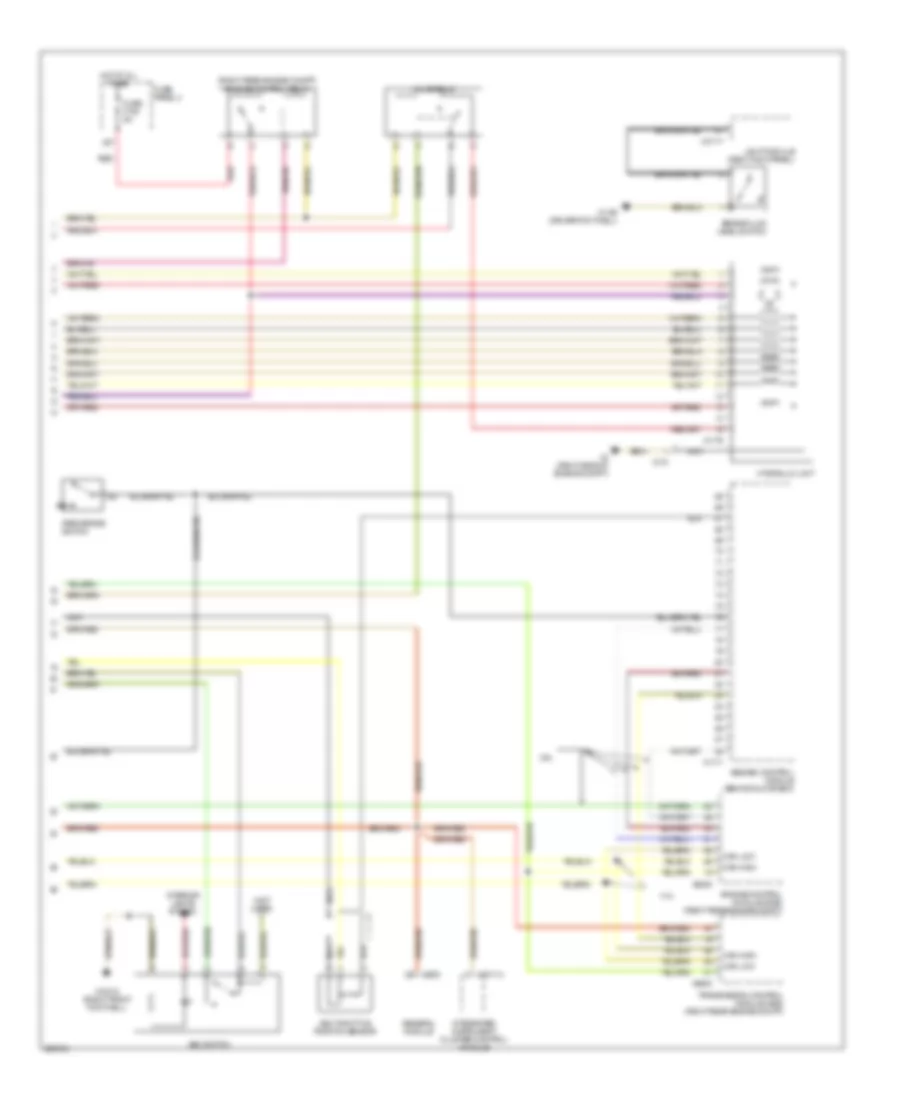
List of elements for Anti-lock Brakes Wiring Diagram (2 of 2) for BMW 528i 1997:
- (not used)
- (right rear engine compt) engine control relay
- 2.8l
- 4.4l
- Abs/asc control module (behind glove box)
- Asc switch
- Asc throttle position sensor
- Brake fluid level switch
- Can high
- Can low
- Engine control module (dme) (right rear engine compt)
- Fuse f108 5a
- Fuse panel 4
- General module
- Hot at all times
- Hydraulic unit
- Integrated instrument cluster control module
- Interior lights system
- Light module (right kick panel)
- Nca
- Park brake switch
- Red
- Transmission control module (ags) (right rear engine compt)
- Valve relay
- X10012 (right front footwell)
- X10114
- X1108 (driver footwell)
- X1171
- X1176
- X170
- X253
- X27
- X4 (right side of engine compt)
- X6000
- X8600
- X10117