ANTI-LOCK BRAKES
Anti-lock Brakes Wiring Diagram (1 of 2) for BMW i3 Range Extender 2014

List of elements for Anti-lock Brakes Wiring Diagram (1 of 2) for BMW i3 Range Extender 2014:
- Body domain controller (lower right side of dash)
- Brake fluid level switch (on brake fluid reservoir)
- Brake light switch (top of brake pedal assembly)
- Center console control panel
- Computer data lines system
- Dynamic stability control (above left front steering control linkage)
- Fuse 40a
- Fuse 50a
- Fuse 5a
- Fuse box (right rear of front compt)
- Hot at all times
- Interior lights system
- Left front brake pad wear sensor (on left front caliper brake assembly)
- Nca
- Power distribution box life module (right side of dash)
- Right rear brake pad wear sensor (on right rear caliper brake assembly)
- X558 1b
- Z10 12b (right rear of front compt)
- Z10 3b (under right side of dash)
- Z10 5b (right rear of front compt)
Anti-lock Brakes Wiring Diagram (2 of 2) for BMW i3 Range Extender 2014
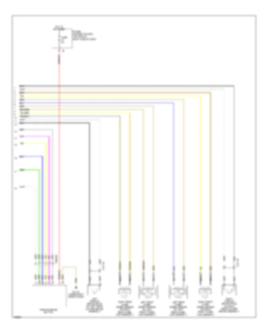
List of elements for Anti-lock Brakes Wiring Diagram (2 of 2) for BMW i3 Range Extender 2014:
- Fuse 5a
- Hot at all times
- Left front wheel speed sensor (on left front wheel hub assembly)
- Left parking brake drive (on left rear caliper brake assembly)
- Left rear wheel speed sensor (on left rear wheel hub assembly)
- Nca
- Parking brake button
- Power distribution box life module (right side of dash)
- Right front wheel speed sensor (on right front wheel hub assembly)
- Right parking brake drive (on right rear caliper brake assembly)
- Right rear wheel speed sensor (on right rear wheel hub assembly)
- X413 1b
- X414 1b
- X558 6b
- Z10 1b (under right side of dash)