ANTI-LOCK BRAKES
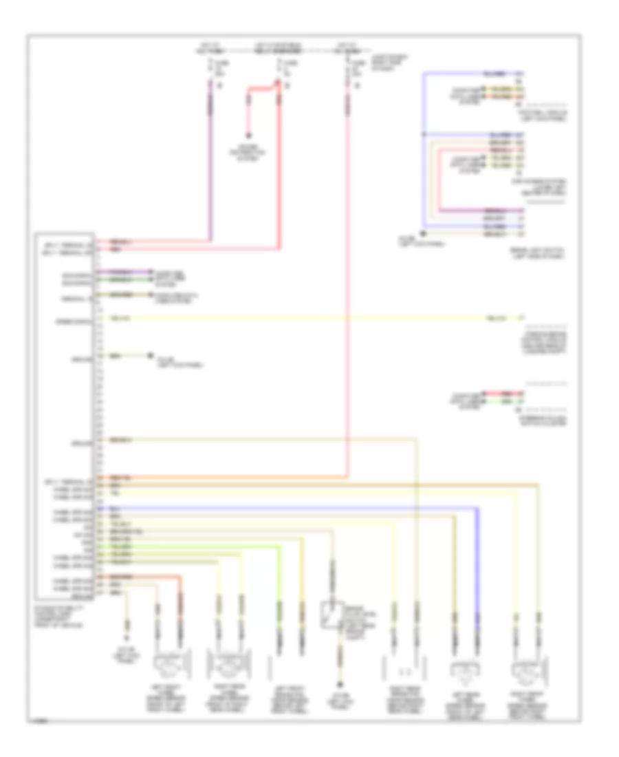
Anti-lock Brakes Wiring Diagram for BMW M5 2013
List of elements for Anti-lock Brakes Wiring Diagram for BMW M5 2013:
- (front of right rear wheel)
- Brake fluid level switch (left rear engine compt)
- Brake light switch (left side of dash)
- Bus signal
- Car access system (lower left center of dash)
- Computer data lines system
- Dynamic stability control (dsc) (under right front of vehicle)
- Footwell module (left kick panel)
- Fuse 30a
- Fuse 50a
- Fuse 5a
- Gnd
- Ground
- Hot at all times
- Hot w/ bi-stable relay energized
- Junction box (right side of dash)
- Left front brake pad wear sensor (behind left front wheel)
- Left front wheel speed sensor (front of left front wheel)
- Left rear wheel speed sensor (front of left rear wheel)
- Nca
- Parking brake control module (center rear of luggage compt)
- Power distribution system
- Red
- Right front wheel speed sensor (behind right front wheel)
- Right rear brake pad wear sensor (behind right rear wheel)
- Right rear wheel speed sensor
- Sig
- Speed signal
- Sply, terminal 30
- Sply, terminal 30f
- Steering column switch cluster
- Sw sig
- Terminal 15
- Wheel spd sig
- Z10 4b (left kick panel)
- Z10 9b (left kick panel)
 English