ANTI-LOCK BRAKES
Anti-lock Brakes Wiring Diagram for BMW X3 35i 2012
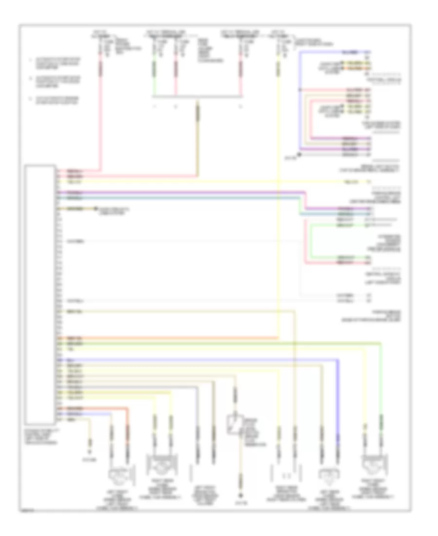
List of elements for Anti-lock Brakes Wiring Diagram for BMW X3 35i 2012:
- (right rear wheel hub assembly)
- Automatic start/stop function w/ one dc/dc converter
- Automatic start/stop function w/ two dc/dc converter
- Brake fluid level switch (brake fluid reservoir)
- Brake light switch (top of brake pedal assembly)
- Car access system (left side of dash)
- Central gateway module (left side of dash)
- Computer data lines system
- Dynamic stability control (dsc) (left side of vehicle chassis)
- Footwell module
- Front power distribution box
- Fuse 30a
- Fuse 50a
- Fuse 5a
- Hot at all times
- Hot w/ terminal 30b relay energized
- Integrated chassis management (center console)
- Junction box (right side of dash)
- Left front brake pad wear sensor (left front caliper)
- Left front wheel speed sensor (left front wheel hub assembly)
- Left rear wheel speed sensor (left rear wheel hub assembly)
- Nca
- Parking brake button (base of parking brake lever)
- Parking brake control unit (center rear cargo area)
- Rear fuse holder (rear compt floor board)
- Right front wheel speed sensor (right front wheel hub assembly)
- Right rear brake pad wear sensor (right rear caliper)
- Right rear wheel speed sensor
- W/o automatic engine start/stop function
- Z10 24b
- Z10 7b
 English