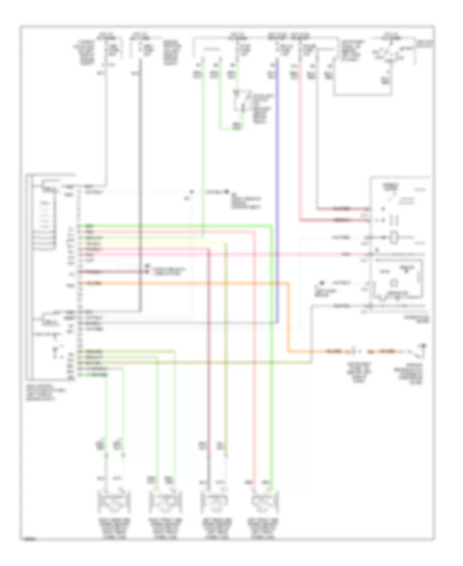
ANTI-LOCK BRAKES
Anti-lock Brakes Wiring Diagram for Scion xA 2004
List of elements for Anti-lock Brakes Wiring Diagram for Scion xA 2004:
- +bm
- +bs
- Abs 1 fuse 40a
- Abs fuse 60a
- Abs ind
- Acc
- Brake ind
- Brl
- C10
- C11
- Combination meter
- Computer data lines system
- D/g
- Ecu ig fuse 7.5a
- Ed (right rear of engine compartment)
- Engine room r/b (on left side of engine compt)
- F10
- Fl+
- Fl-
- Fr+
- Fr-
- Fusible link block (on left side of engine compt)
- G13
- Gauge fuse 10a
- Gnd1
- Gnd2
- Hot at all times
- Hot in on or start
- If (left dash brace)
- Ig1
- Ignition switch
- Instrument panel j/b (behind left side of dash)
- Left front abs speed sensor (mounted on left front wheel hub)
- Left rear abs speed sensor (mounted on left rear wheel hub)
- Lock
- Off
- Parking brake switch (on base of park brake lever)
- Pkb
- Pnk
- Red
- Relay
- Right front abs speed sensor (mounted on right front wheel hub)
- Right rear abs speed sensor (mounted on right rear wheel hub)
- Rl+
- Rl-
- Rr+
- Rr-
- Skid control actuator with ecu (left side of engine compt)
- Sp1
- Speedo- meter
- Start
- Stop fuse 10a
- Stoplight switch (on bracket, above brake pedal)
- Stp
 English