COMPUTER DATA LINES
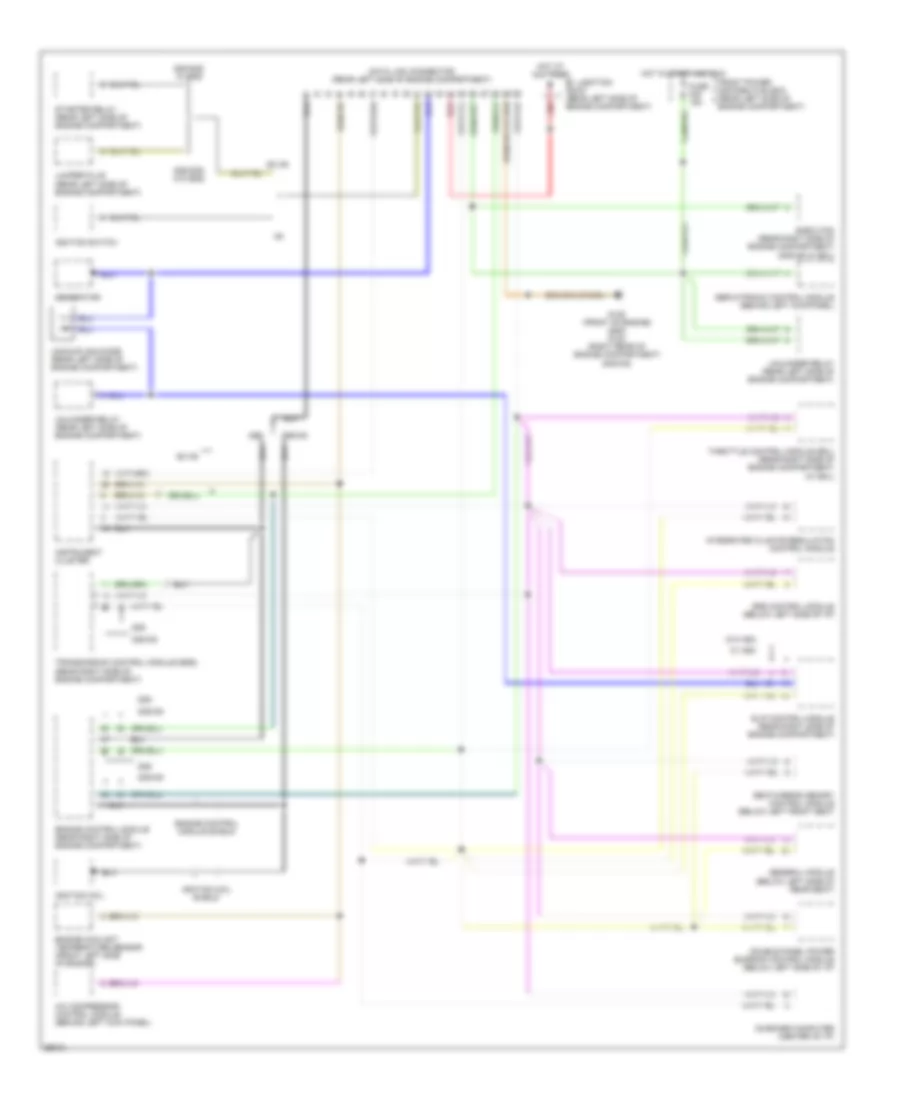
Data Link Connector Wiring Diagram for BMW 535i 1993
List of elements for Data Link Connector Wiring Diagram for BMW 535i 1993:
- 525i
- 525i/535i w/ egs
- 525i/535i w/o egs
- 535i/m5
- A/c compressor control module (behind left kick panel)
- B+ junction point (rear left side of engine compartment)
- Data link connector (rear left side of engine compartment)
- Double panel power sunroof control module (below left side of i/p)
- E-box fan (rear right side of engine compartment) (535i/m5 w/ eml)
- Engine control module (rear right side of engine compartment)
- Engine control module shield
- Engine coolant temperature sensor (front left side of engine)
- Ex m5
- Front power distribution box (rear left side of engine compartment)
- Fuse f28 15a
- G125 (front of engine) (525i) g123 (right rear of engine compartment) (535i/m5)
- General module (below left side of rear seat)
- Generator
- Hot at all times
- Hot in start and run
- Ignition coil
- Ignition coil shield
- Ignition switch
- Instrument cluster
- Integrated climate regulation control module
- Jumper plug (rear left side of engine compartment)
- On-board computer (center of i/p)
- Red
- Seat/mirror memory control module (below left front seat
- Servotronic control module (behind left kickpanel)
- Slip control module (rear right side of engine compartment)
- Srs control module (below left side of i/p)
- Starter relay (rear left side of engine compartment)
- Throttle control module (eml) (rear right side of engine compartment) (w/ eml)
- Transmission control module (egs) (rear right side of engine compartment)
- Uncoupling diode (rear left side of engine compartment)
- Unloader relay (rear left side of engine compartment)
- W/ asc
- W/o asc
 English