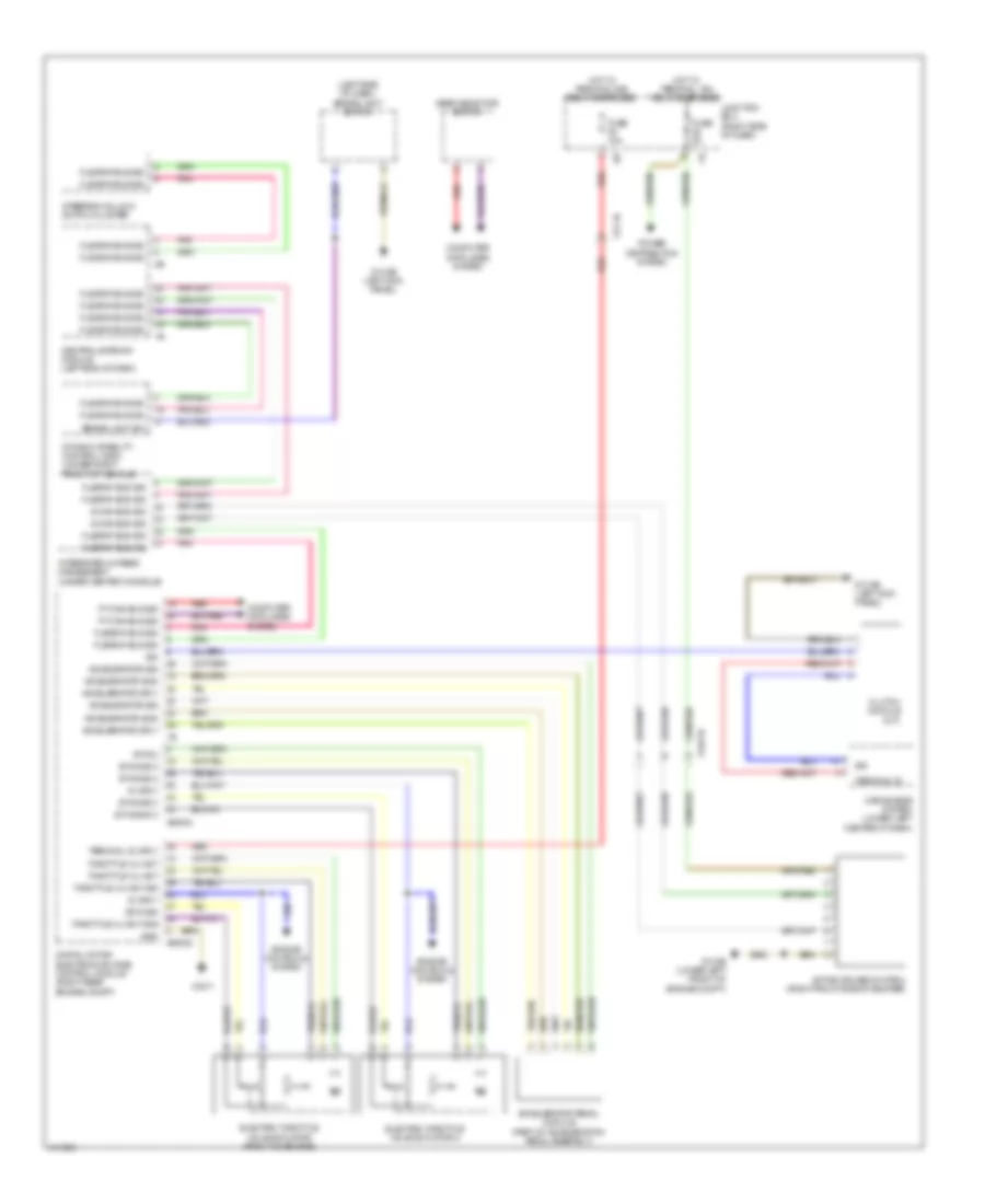
CRUISE CONTROL
Cruise Control Wiring Diagram for BMW 550xi GT 2013
List of elements for Cruise Control Wiring Diagram for BMW 550xi GT 2013:
- (left side of dash) brake light switch
- 5v sply
- Accelerator gnd
- Accelerator pedal module (part of acceleration pedal assembly)
- Accelerator sig
- Accelerator sply
- Active cruise control (right front side of bumper)
- Brake light sw
- Car access system (lower left center of dash)
- Central gateway module (left end of dash)
- Clutch module (m/t)
- Computer data lines system
- Digital motor electronics (dme) control module (right rear engine compt)
- Dynamic stability control (dsc) (under right front of vehicle)
- Electric throttle valve actuator (front of engine)
- Electric throttle valve actuator 2
- Engine controls system
- Etva 2
- Etva gnd 2
- Etva sig
- Etva sig 2
- Flexray bus sig
- Fuse 10a
- Fuse 5a
- Gear selector switch
- Gnd
- Hot w/ terminal 15n relay energized
- Hot w/ terminal 30b relay energized
- Integrated chassis management (under center console)
- Junction box (right side of dash)
- Pnk
- Power distribution system
- Pt-can bus sig
- Red
- S-can bus sig
- Sig
- Steering column switch cluster
- Terminal 30
- Terminal 30, sply
- Throttle vlv act
- Throttle vlv act gnd
- Throttle vlv act sig
- X13 1b
- X148 1b
- X60002
- X60004
- X7517
- Z10 2b (lower left front of engine compt)
- Z10 9b (left kick panel)
 English