ENGINE PERFORMANCE
3.0L TWIN TURBO
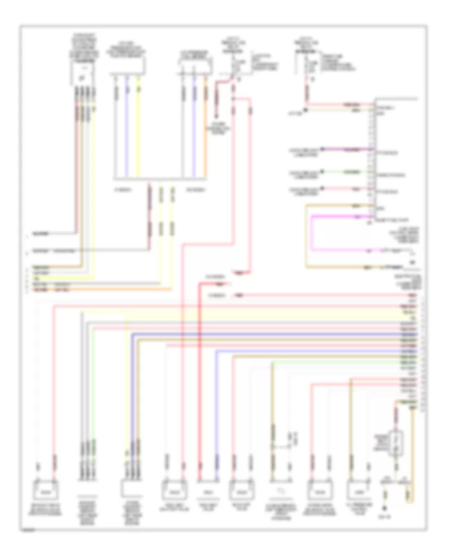
3.0L Twin Turbo, Engine Performance Wiring Diagram (1 of 5) for BMW 640i 2012

List of elements for 3.0L Twin Turbo, Engine Performance Wiring Diagram (1 of 5) for BMW 640i 2012:
- (front of intake manifold) intake-manifold pressure sensor
- (on exhaust manifold) oxygen sensor before catalytic converter
- (right side of engine) knock sensor
- Activation throttle vlv act
- Activation vlv
- Activation vol ctrl vlv
- Bsd bus sig
- Cooling fans system
- Crankshaft position sensor (lower front of engine)
- Crankshaft sens sig
- Cylinder 1-3
- Cylinder 4-6
- Digital motor electronics (dme) control module (right front of engine compt)
- Early production
- Elec throttle act gnd
- Elec throttle vlv act sig
- Electromotive throttle actuator
- Gnd crankshaft sens
- Gnd int air temp pres snsr
- Gnd intake pipe pres snsr
- Gnd oil condition sens
- High pres pump contl gnd
- High pres pump contl sig
- High pres pump contl sply
- Intake air temperature pressure sensor (front of intake manifold)
- Knock sens sig
- Late production
- Nca
- Oil condition sensor (w/ bosch) oil level sensor (w/o bosch) (w/ bosch: bottom of engine oil pan)
- Oxy sens sig
- Oxygen sens gnd
- Oxygen sens sig
- Pres sens sig
- Quality control valve
- Sens gnd
- Sply additional coolant pump
- Sply crankshaft sens
- Sply elect throttle vlv act
- Sply int air temp pres sens
- Sply int pipe pres sens
- Sply oil condition sens
- Sply oxy sens aft cat conv
- Sply oxy sens bef cat conv
- Sply vol ctrl vlv
- Starting/ charging system
- Temp sens sig
- W/ bosch
- W/o bosch
- Wastegate valve pressure converter
- Wastegate vlv sply pres conv
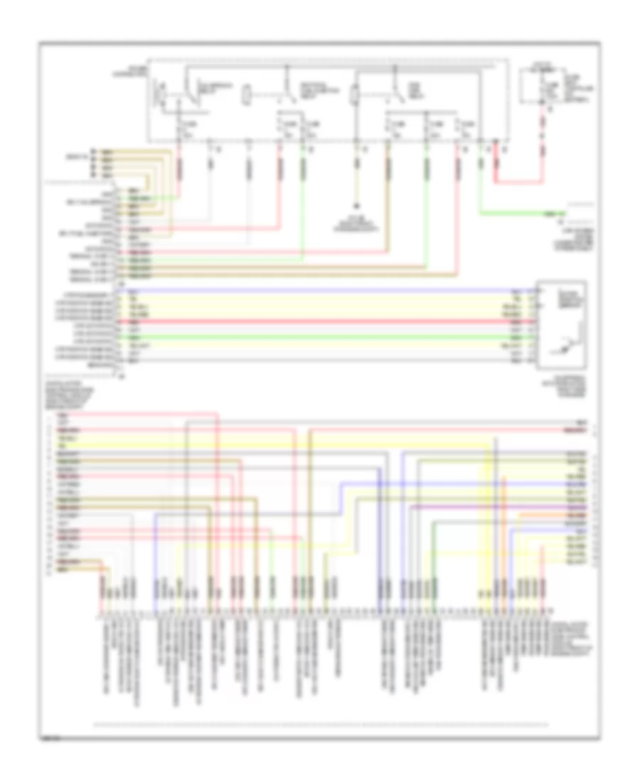
3.0L Twin Turbo, Engine Performance Wiring Diagram (2 of 5) for BMW 640i 2012
List of elements for 3.0L Twin Turbo, Engine Performance Wiring Diagram (2 of 5) for BMW 640i 2012:
- (in exhaust, downstream of catalytic converter) oxygen sensor after catalytic converter
- (on high pressure pump) high pressure pump position sensor
- Blow-off valve
- Characteristic map thermostat (front of engine)
- Computer data lines system
- Elect fuel pump
- Electric fuel pump (under right rear seat)
- Engine venti- lation heating
- Exhaust camshaft sensor (left rear side of engine)
- Exhaust vanos solenoid valve (front of engine)
- Fuel pump control (ekps) (under right rear seat)
- Fuse 20a
- Fuse 5a
- Gnd
- Hot w/ terminal 30b relay energized
- Intake camshaft sensor (left rear side of engine)
- Intake vanos solenoid valve (front of engine)
- Junction box (under right side of dash)
- Low pressure fuel sensor
- Nca
- Oil pressure control valve
- Power distribution system
- Pt can bus
- Pwr sply
- Rear fuse carrier (in rear power distribution box)
- Red
- Tank vent shut-off valve
- Tank vent valve
- W/ bosch
- W/o bosch
- Wake up signal
- X705 1b
- Z10 18b
- Z23 1b
3.0L Twin Turbo, Engine Performance Wiring Diagram (3 of 5) for BMW 640i 2012
List of elements for 3.0L Twin Turbo, Engine Performance Wiring Diagram (3 of 5) for BMW 640i 2012:
- Activation
- Activation char map thermostat
- Activation elect changeover vlv
- Activation oil pres ctrl vlv
- Activation tank vent vlv
- Bosch gnd
- Car access system (under center of rear shelf)
- Digital motor electronics (dme) control module (right front of engine compt)
- Dme main relay
- Eng coolant temp sens gnd
- Engine oil pres sens gnd
- Engine oil pres sens sply
- Engine oil temp snsr
- Exhaust activation vanos sol vlv
- Exhaust camshaft sens sig
- Fuse 100a
- Fuse 15a
- Fuse 20a
- Fuse 40a
- Fuse box (installed on battery)
- Gnd
- Gnd exhaust camshaft snsr
- Gnd hot-film air mass meter
- Gnd intake camshaft snsr
- Hi pressure sig
- Hot at all times
- Hot-film air mass meter sig
- Ign sply
- Ignition & fuel injection relay
- Int activation vanos sol vlv
- Int camshaft sens sig
- Int sply vanos sol vlv
- Motor position sensor
- Mtr activation
- Mtr pos snse sply
- Mtr position snse sig
- Oil press ctrl vlv sply
- Power distribution
- Pres sens sig
- Rail pres sens gnd
- Rail pres sens sply
- Red
- Sens gnd
- Sply bosch pump
- Sply char map thermostat
- Sply elect changeover vlv
- Sply eng breather heater 1
- Sply exhaust camshaft snsr
- Sply fuel injectors
- Sply hi pressure
- Sply hot-film air mass meter
- Sply int camshaft snsr
- Sply valvetronic
- Temp sens sig
- Terminal 15 sply
- Valvetronic actuator motor (right side of engine)
- Valvetronic relay
- Ventilation activation
- Z10 3b (right front of engine compt)
- Z6000 1b
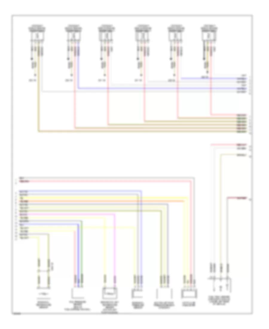
3.0L Twin Turbo, Engine Performance Wiring Diagram (4 of 5) for BMW 640i 2012
List of elements for 3.0L Twin Turbo, Engine Performance Wiring Diagram (4 of 5) for BMW 640i 2012:
- (top right side of engine) ignition coil 1
- (top right side of engine) ignition coil 2
- (top right side of engine) ignition coil 3
- (top right side of engine) ignition coil 4
- (top right side of engine) ignition coil 5
- (top right side of engine) ignition coil 6
- Engine coolant temperature sensor (on coolant pump housing)
- Engine oil pressure sensor
- Engine oil temperature sensor
- Fuel tank leakage diagnostic module (under left rear of vehicle)
- Hot-film air mass meter
- Nca
- Plug spark
- Rail pressure sensor (end of fuel-distribution rail)
- Spark plug
- Suction jet pump pressure sensor (w/ bosch)
- X704 1b
- Z20 1b
- Z21 1b
- Z22 1b
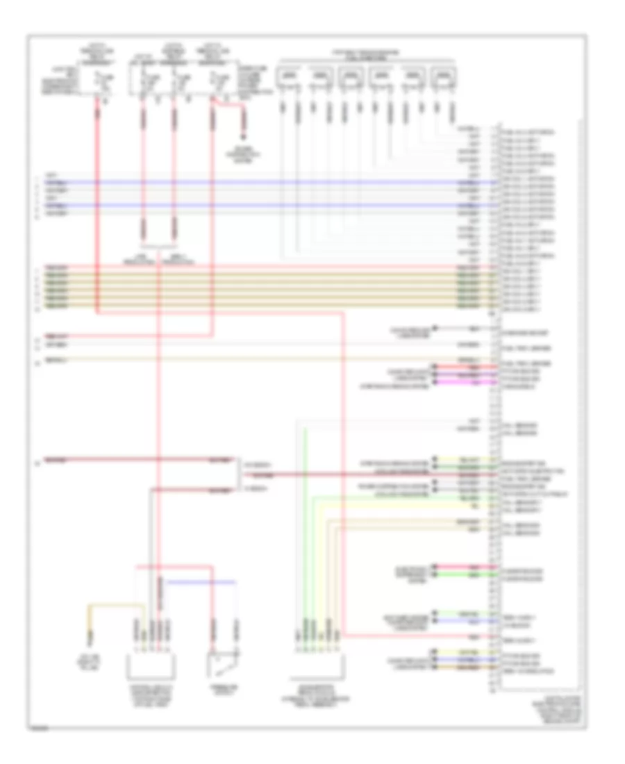
3.0L Twin Turbo, Engine Performance Wiring Diagram (5 of 5) for BMW 640i 2012
List of elements for 3.0L Twin Turbo, Engine Performance Wiring Diagram (5 of 5) for BMW 640i 2012:
- (top right side of engine) fuel injectors
- 11b
- Accelerator pedal module (integral to accelerator pedal assembly)
- Activation cut-out relay
- Activation electric fan
- Anti-theft system computer data lines system
- Cas sub-bus
- Computer data lines system
- Cooling fans system
- Diagnosis socket
- Digital motor electronics (dme) control module (right front of engine compt)
- Early production
- Electronic suspension system
- Engine start sig
- Flexray bus sig
- Fuel inj 1 activation
- Fuel inj 1 sply
- Fuel inj 2 activation
- Fuel inj 2 sply
- Fuel inj 3 activation
- Fuel inj 3 sply
- Fuel inj 4 activation
- Fuel inj 4 sply
- Fuel inj 5 activation
- Fuel inj 5 sply
- Fuel inj 6 activation
- Fuel inj 6 sply
- Fuel tank leakage
- Fuse 15a
- Fuse 5a
- Hall sens gnd
- Hall sens sig
- Hall sens sply
- Hot at all times
- Hot w/ bistable relay energized
- Hot w/ terminal 30b relay energized
- Ign coil 1 activation
- Ign coil 1 sply
- Ign coil 2 activation
- Ign coil 2 sply
- Ign coil 3 activation
- Ign coil 3 sply
- Ign coil 4 activation
- Ign coil 4 sply
- Ign coil 5 activation
- Ign coil 5 sply
- Ign coil 6 activation
- Ign coil 6 sply
- Junction box electronics (under right side of dash)
- Late production
- Lin bus sig
- Natural vacuum leak detection (top right side of fuel tank)
- Pnk
- Power distribution system
- Pressure switch
- Pt-can bus sig
- Rear fuse holder (in rear power distribution box)
- Red
- Starting/charging system
- Term 15 sply
- Term 15 wake up sig
- Term 30 sply
- W/ bosch
- W/o bosch
- Z10 13b (right "c" pillar)