ENGINE PERFORMANCE
3.0L TWIN TURBO
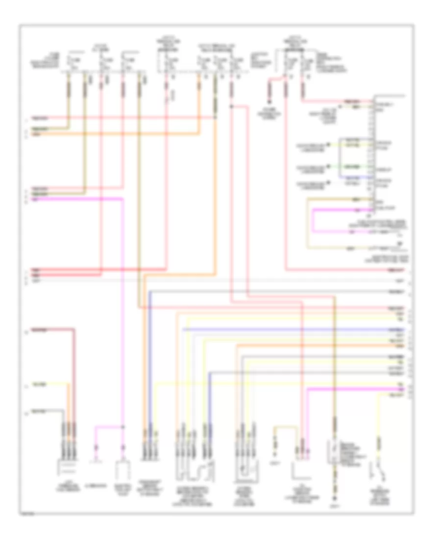
3.0L Twin Turbo, Engine Performance Wiring Diagram (1 of 5) for BMW 740i 2011

List of elements for 3.0L Twin Turbo, Engine Performance Wiring Diagram (1 of 5) for BMW 740i 2011:
- 5 v sply
- Air ctrl vlv
- Bsd bus sig
- Coolant pump sply
- Ctrl vlv
- Digital motor electronics (dme) control module (right front of engine compt)
- Diverter valve
- Electric coolant pump
- Fuel injector
- Fuse 100a
- Fuse box (center of luggage compt)
- Hot at all times
- Intake air temperature/ boost pressure sensor (on right intake air duct)
- Intake pipe pressure sensor
- Load shedding relay
- Map thermostat
- Pressure converter wastegate valve (front of engine)
- Pressure converter wastegate valve 2 (front of engine)
- Pressure sens
- Rail pressure sens
- Rail pressure sensor (lower right front of engine)
- Red
- Sens
- Sens gnd
- Sens sig
- Sens sply
- Terminal 15
- Terminal 30
- Terminal 87
- Volume control valve (lower left rear of engine)
- Wastegate valve
- Wastegate valve 2
- X168 1b
- X60002
- X6455
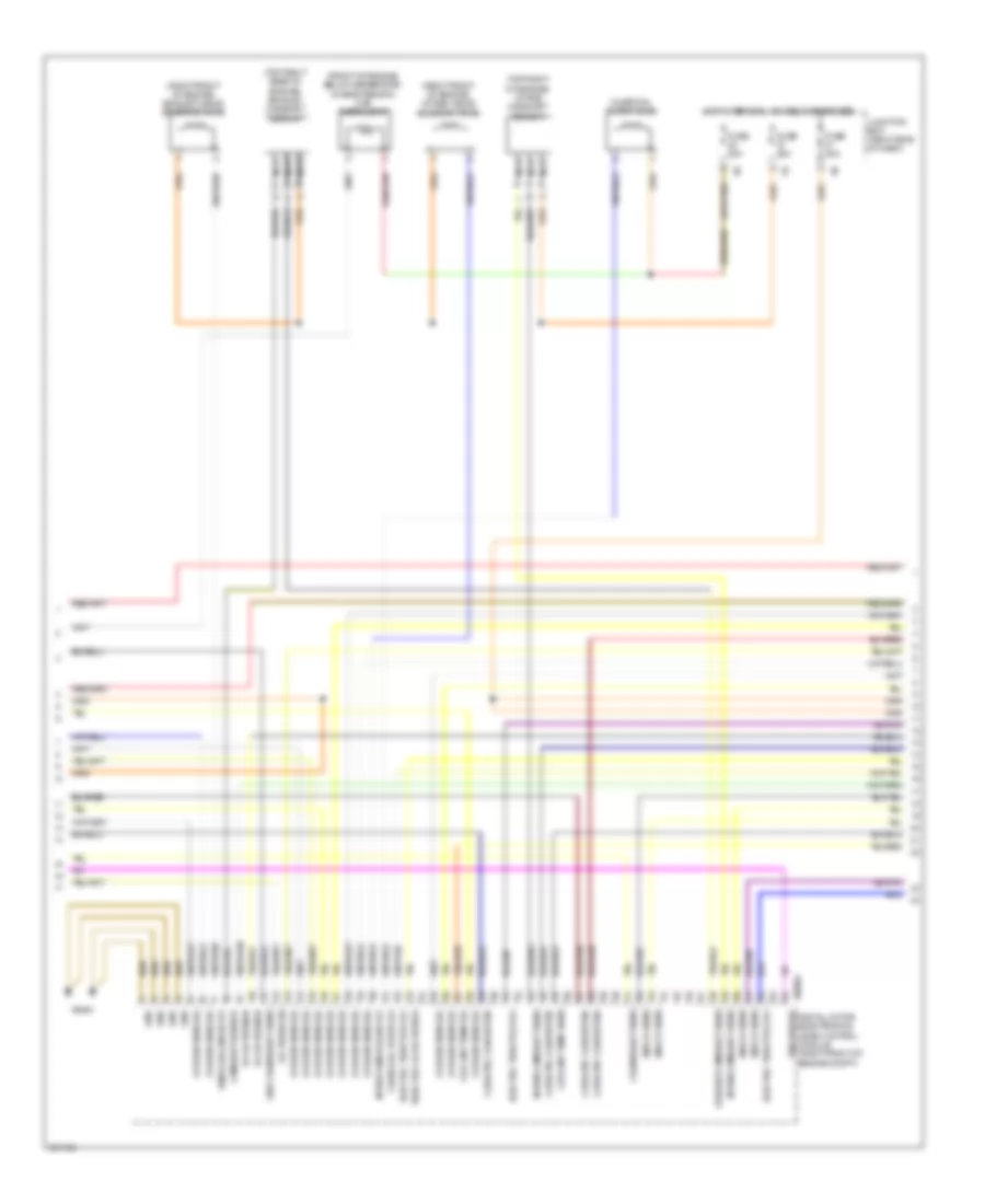
3.0L Twin Turbo, Engine Performance Wiring Diagram (2 of 5) for BMW 740i 2011
List of elements for 3.0L Twin Turbo, Engine Performance Wiring Diagram (2 of 5) for BMW 740i 2011:
- Alternator
- Can bus
- Computer data lines system
- Crankshaft sensor (bottom right of engine)
- Electric coolant pump
- Electric fuel pump (top right of fuel tank)
- Engine breather heater 1 (lower right side of of engine)
- Fuel pump
- Fuel pump control (ekps) (right rear of luggage compt)
- Fuse 15a
- Fuse 20a
- Fuse 30a
- Fuse 50a
- Fuse 5a
- Fuse holder (right front of engine compt)
- Gnd
- Hot at all times
- Hot w/ terminal 15n relay energized
- Hot w/ terminal 30b relay energized
- Junction box (right side of dash)
- Low pressure fuel sensor
- Nca
- Oil condition sensor (lower right rear of engine)
- Oil pressure switch (left rear of engine)
- Oxygen sensor 2 after catalytic converter
- Oxygen sensor 2 before catalytic converter (before right catalytic converter)
- Power distribution system
- Pt can
- Pwr sply
- Rear distribution box (right rear of luggage compt)
- Red
- Wake up
- X13 1b
- X7517
- X8681
- X8682
- X8683
- Z10 17b (right rear of luggage compt)
3.0L Twin Turbo, Engine Performance Wiring Diagram (3 of 5) for BMW 740i 2011
List of elements for 3.0L Twin Turbo, Engine Performance Wiring Diagram (3 of 5) for BMW 740i 2011:
- (front of engine, below generator) characteristic map thermostat
- (right front of engine) exhaust vanos solenoid valve
- (right front of engine) intake vanos solenoid valve
- (top right of engine) intake camshaft sensor
- (top right rear of engine) exhaust camshaft sensor
- Bsd bus sig
- Camshaft sensor
- Catalytic converter
- Charcoal filter valve
- Charcoal filter vlv
- Coolant temp sens
- Coolant temp sig
- Crankshaft sens
- Digital motor electronics (dme) control module (right front of engine compt)
- Electric throttle vlv
- Exhuast camshaft sens
- Fuse 20a
- Fuse 30a
- Gnd
- Gnd crankshaft sens
- Hot w/ terminal 15n relay energized
- Intake camshaft sens
- Intake vanos slnd vlv
- Junction box (right side of dash)
- Knock sens
- Nca
- Oil press sw
- Oxygen sens sig
- Throttle vlv actuator
- Vanos solenoid vlv
- Vlv activation
- X60004
- X6454
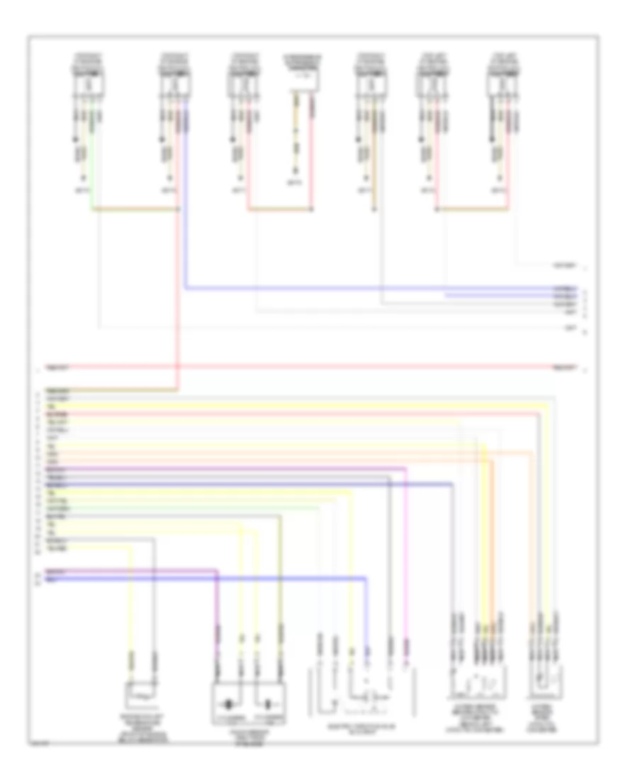
3.0L Twin Turbo, Engine Performance Wiring Diagram (4 of 5) for BMW 740i 2011
List of elements for 3.0L Twin Turbo, Engine Performance Wiring Diagram (4 of 5) for BMW 740i 2011:
- (top left of engine) ignition coil cylinder 5
- (top left of engine) ignition coil cylinder 6
- (top right of engine) ignition coil cylinder 1
- (top right of engine) ignition coil cylinder 2
- (top right of engine) ignition coil cylinder 3
- (top right of engine) ignition coil cylinder 4
- Cylinders 1-3
- Cylinders 4-6
- Electric throttle valve actuator
- Engine coolant temperature sensor (front of engine, below generator)
- Interference suppression capacitor
- Knock sensor (right side of engine)
- Nca
- Oxygen sensor after catalytic converter
- Oxygen sensor before catalytic converter (behind left catalytic converter)
- Plug spark
- Spark plug
- X6170
- X6171
- X6172
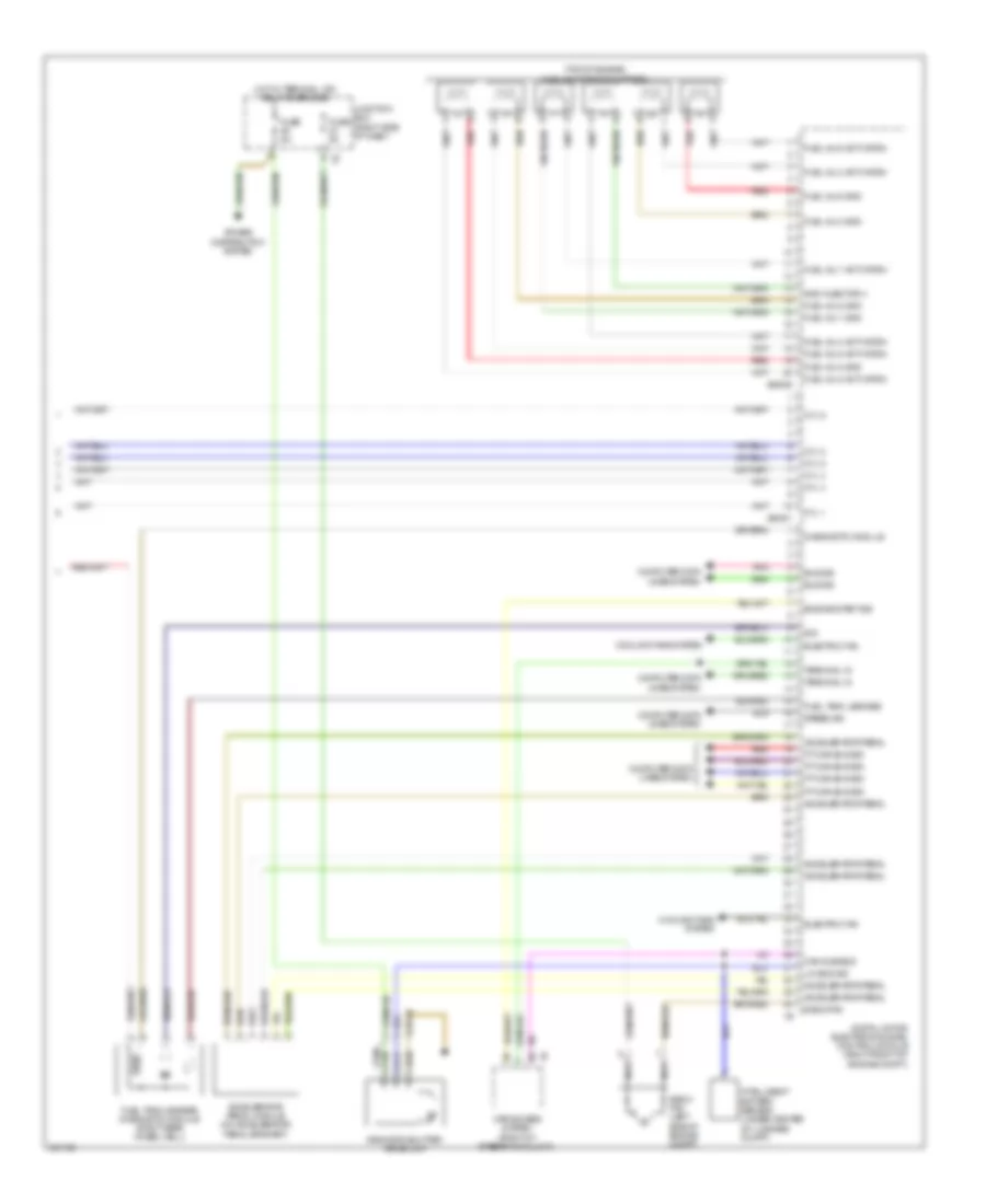
3.0L Twin Turbo, Engine Performance Wiring Diagram (5 of 5) for BMW 740i 2011
List of elements for 3.0L Twin Turbo, Engine Performance Wiring Diagram (5 of 5) for BMW 740i 2011:
- (top of engine) fuel injector cylinders
- Accelerator pedal
- Accelerator pedal module (on accelerator pedal bracket)
- Bus sig
- Can sub-bus
- Car access system (right of steering column)
- Computer data lines system
- Cooling fans system
- Cyl 1
- Cyl 2
- Cyl 3
- Cyl 4
- Cyl 5
- Cyl 6
- Diagnostic module
- Digital motor electronics (dme) control module (right front of engine compt)
- E-box fan
- E-box fan (left side of engine compt)
- Electric fan
- Engine start sig
- Fuel inj 1 activation
- Fuel inj 1 gnd
- Fuel inj 2 activation
- Fuel inj 2 gnd
- Fuel inj 3 activation
- Fuel inj 3 gnd
- Fuel inj 4 activation
- Fuel inj 5 activation
- Fuel inj 5 gnd
- Fuel inj 6 activation
- Fuel inj 6 gnd
- Fuel tank leakage
- Fuel tank leakage diagnostic module (right rear wheel well)
- Fuse 5a
- Gnd injector 4
- Hot w/ terminal 15n relay energized
- Intelligent battery sensor (under center of luggage compt)
- Junction box (right side of dash)
- Lin bus sig
- Nca
- Pnk
- Power distribution system
- Pt-can bus sig
- Radiator shutter drive unit
- Red
- Sig
- Speed sig
- Terminal 15
- X148 1b
- X60001
- X60005