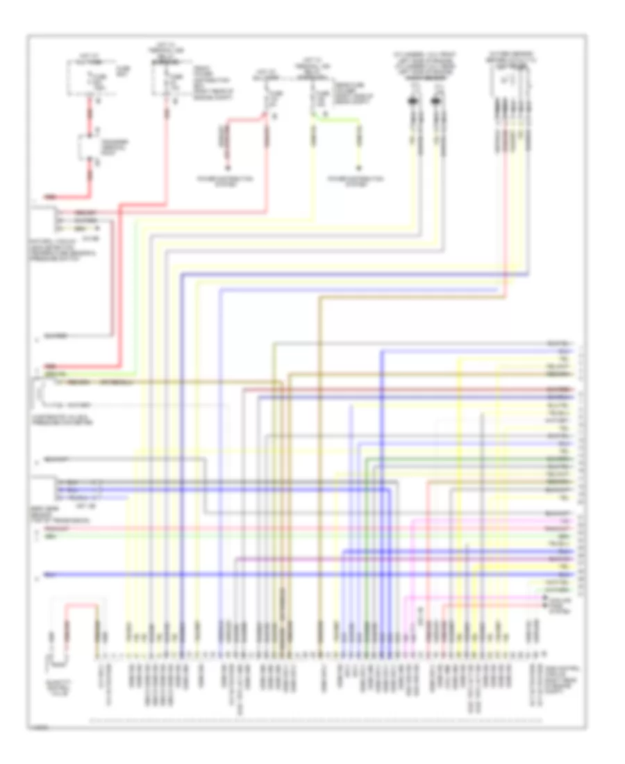
ENGINE PERFORMANCE
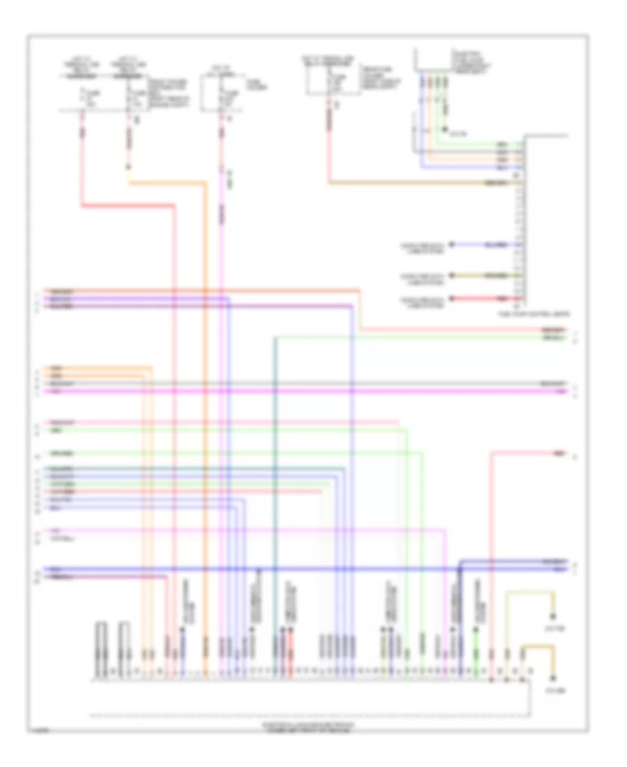
3.0L TURBO HYBRID
3.0L Turbo Hybrid, Engine Performance Wiring Diagram (1 of 7) for BMW ActiveHybrid 3 2013

List of elements for 3.0L Turbo Hybrid, Engine Performance Wiring Diagram (1 of 7) for BMW ActiveHybrid 3 2013:
- (pins 16 to 19 not used)
- (under engine valve cover) valvetronic servomotor
- Accelerator pedal module (part accelerator pedal assembly)
- Brake vacuum/ pressure sensor (on brake vacuum booster assembly)
- Computer data lines system
- Cooling fans system
- Cut-out relay
- Diagnosis jack
- Dme control module (right rear of engine compt)
- Dme main relay
- Electric fan
- Electrical exhaust flap (left side of rear compt)
- Electronic coolant pump 2
- Eng strt sig
- Environmental air catalyst sensor
- Flap activation
- Flexray bus sig
- Front electronic module (right end of dash)
- Fuel
- Fuel inj activation
- Fuel inj sply
- Fuel tank pressure sensor
- Fuse 15a
- Fuse 20a
- Fuse 40a
- Fuse 5a
- Gnd
- Hall sens gnd
- Hall sens sig
- Hall sens sply
- Hot w/ terminal 30b relay energized
- Ignition & fuel injection relay
- Leak detection sig
- Lin bus sig
- Motor position sensor
- Mtr activation
- Nca
- Pnk
- Power distribution box (right rear of engine compt)
- Pt-can bus sig
- Pt-can bus sig term 15 wake up sig
- Rear fuse holder (right side of rear compt)
- Red
- Rly activation
- Sens gnd
- Sens sig
- Sens sply
- Spd sig
- Sply
- Tank locking valve
- Term 15 sply
- Valvetronic relay
- Vlv sply
- Z10 2b
- Z10 6b
- Z10 9b
- Z11 3b
- Z11 4b
- Z6000 1b
- Z8 3b
- Z8 4b
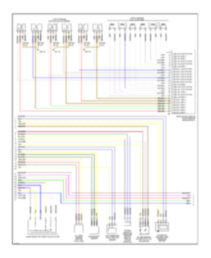
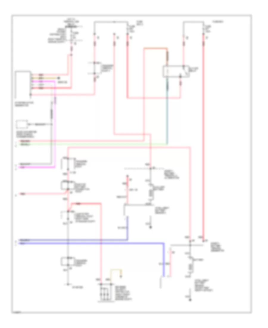
3.0L Turbo Hybrid, Engine Performance Wiring Diagram (2 of 7) for BMW ActiveHybrid 3 2013
List of elements for 3.0L Turbo Hybrid, Engine Performance Wiring Diagram (2 of 7) for BMW ActiveHybrid 3 2013:
- (cylinders 1 & 2: front left side of engine) (cylinders 3 & 4: rear left side of engine) knock sensor
- (right rear of engine compt)
- Act activation
- Bsd bus sig
- Cool pmp
- Cooling fans system
- Cyl 1-3
- Cyl 4-6
- Dme control module
- Elec trtl act gnd
- Elec trtl act sig
- Front power distribution box (right rear of engine compt)
- Fuse 10a
- Fuse 125a
- Fuse 15a
- Fuse 5a
- Fuse box
- Hot at all times
- Hot w/ terminal 15n relay energized
- Hot w/ terminal 30b relay energized
- Knock sens sig
- Natural vacuum leak detection temperature sensor & pressure switch
- Nca
- Oxygen sensor before catalytic converter
- Power distribution system
- Quantity control valve
- Rear fuse holder (right side of rear compt)
- Red
- Sens gnd
- Sens sig
- Sens sply
- Sply
- Transfer terminal point
- Vlv activation
- Vlv sply
- Wastegate valve & pressure converter
- X671 2b
- X671 3b
- Z10 9b
- Zero gear sensor (top of transmission)
3.0L Turbo Hybrid, Engine Performance Wiring Diagram (3 of 7) for BMW ActiveHybrid 3 2013
List of elements for 3.0L Turbo Hybrid, Engine Performance Wiring Diagram (3 of 7) for BMW ActiveHybrid 3 2013:
- (top of engine) fuel injectors
- (top of engine) ignition coil cylinders
- Crankshaft sensor
- Dme control module (right rear of engine compt)
- Electromotive throttle actuator
- Fuel inj 1 activation
- Fuel inj 1 sply
- Fuel inj 2 activation
- Fuel inj 2 sply
- Fuel inj 3 activation
- Fuel inj 3 sply
- Fuel inj 4 activation
- Fuel inj 4 sply
- Fuel inj 5 activation
- Fuel inj 5 sply
- Fuel inj 6 activation
- Fuel inj 6 sply
- High pressure pump position sensor
- Ign coil 1 activation
- Ign coil 1 sply
- Ign coil 2 activation
- Ign coil 2 sply
- Ign coil 3 activation
- Ign coil 3 sply
- Ign coil 4 activation
- Ign coil 4 sply
- Ign coil 5 activation
- Ign coil 5 sply
- Ign coil 6 activation
- Ign coil 6 sply
- Intake air temperature pressure sensor
- Intake- manifold pressure sensor (rear of intake manifold)
- Nca
- Oil level sensor (bottom of oil pan)
- Oxygen sensor after catalytic converter
- Spark plug
- Z20 1b
- Z21 1b
- Z22 1b
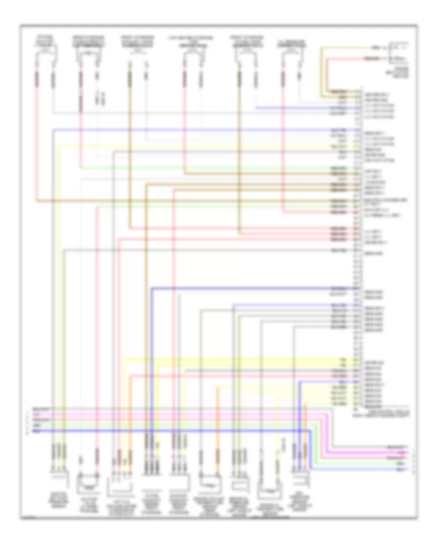
3.0L Turbo Hybrid, Engine Performance Wiring Diagram (4 of 7) for BMW ActiveHybrid 3 2013
List of elements for 3.0L Turbo Hybrid, Engine Performance Wiring Diagram (4 of 7) for BMW ActiveHybrid 3 2013:
- (front of engine)
- (rear of engine) characteristic map thermostat
- (top center of engine)
- Bypass blow-off valve
- Dme control module (right rear of engine compt)
- Electric changeover vlv sply
- Engine coolant temperature sensor (rear of engine)
- Engine oil pressure sensor (left side of engine)
- Engine oil temperature sensor (left side of engine)
- Engine ventilation heating
- Exhaust camshaft sensor (front of engine)
- Exhaust vanos solenoid valve
- Heater gnd
- Heater sply
- Hot film air mass meter (in engine air intake duct)
- Intake camshaft sensor (front of engine)
- Intake vanos solenoid valve
- Lin bus sig
- Map activation
- Map sply
- Meter gnd
- Meter sig
- Meter sply
- Nca
- Oil press vlv sply
- Oil pressure control valve
- Rail pressure sensor (left side of engine)
- Sens gnd
- Sens sig
- Sens sply
- Shutoff valve (w/ sport package)
- Shutoff vlv
- Suction jet pump pressure sensor
- Tank venting valve
- Vlv activation
- Vlv sply
- X704 1b
- X705 1b
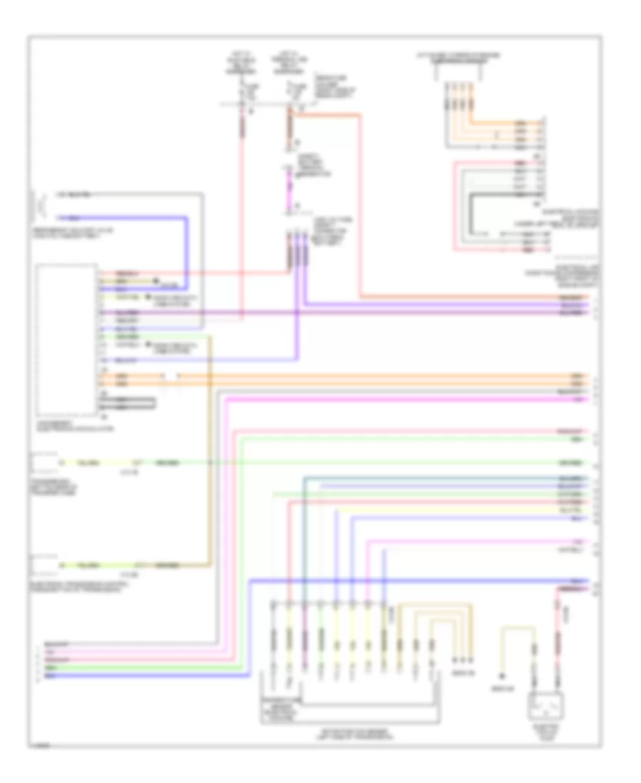
3.0L Turbo Hybrid, Engine Performance Wiring Diagram (5 of 7) for BMW ActiveHybrid 3 2013
List of elements for 3.0L Turbo Hybrid, Engine Performance Wiring Diagram (5 of 7) for BMW ActiveHybrid 3 2013:
- (attached to rear of engine) electrical machine
- Computer data lines system
- Electric vacuum pump
- Electrical air conditioning compressor (right front of engine compt)
- Electrical machine electronics (under left front of vehicle)
- Electronic transmission control (inside bottom of transmission)
- Fuse 5a
- Fuse 7.5a
- High voltage safety connector (on hybrid 1b battery)
- Hot w/ bi-stable relay energized
- Hot w/ terminal 30b relay energized
- Management electronics accumulator
- Nca
- Rear fuse holder (right side of rear compt)
- Red
- Refrigerant shutoff valve (high-voltage battery)
- Rotor position sensor (left side of transmission)
- Safety battery terminal generator 2b
- Temperature sensor (electrical machine)
- Transfer box (bottom rear of transfer case)
- X13 1b
- X13 2b
- X13 8b
- X13 9b
- Z10 8b
- Z6000 2b
- Z6000 3b
3.0L Turbo Hybrid, Engine Performance Wiring Diagram (6 of 7) for BMW ActiveHybrid 3 2013
List of elements for 3.0L Turbo Hybrid, Engine Performance Wiring Diagram (6 of 7) for BMW ActiveHybrid 3 2013:
- 10b
- 11b
- Air conditioning system
- Computer data lines system
- Electric fuel pump (under right rear seat)
- Electrical machine electronics (under left front of vehicle)
- Front power distribution box (right rear of engine compt)
- Fuel pump control (ekps)
- Fuse 10a
- Fuse 20a
- Fuse 40a
- Fuse 5a
- Fuse holder
- Hot at all times
- Hot w/ teminal 30b relay enerziged
- Hot w/ terminal 30b relay energized
- Nca
- Rear fuse holder (right side of rear compt)
- Red
- System air conditioning
- X601 1b
- Z10 29b
- Z10 70b
- Z10 7b
3.0L Turbo Hybrid, Engine Performance Wiring Diagram (7 of 7) for BMW ActiveHybrid 3 2013
List of elements for 3.0L Turbo Hybrid, Engine Performance Wiring Diagram (7 of 7) for BMW ActiveHybrid 3 2013:
- Auxiliary battery
- Battery
- Cut-off relay
- Dc/dc converter (right plenum chamber e-box)
- Front power distribution box (right rear of engine compt)
- Fuse 100a
- Fuse 5a
- Fuse box
- Fuse box 2
- Hot w/ terminal 30b relay energized
- Intelligent battery sensor 2
- Jump start terminal point (right side of engine compt)
- Nca
- Positive battery connection point
- Red
- Red 1b
- Red x1 1b
- Reverse polarity protection (right front corner of engine compt)
- Safety battery terminal 2 alternator
- Safety battery terminal generator
- Starter
- Starter motor generator
- Transfer terminal point
- Transfer terminal point 3
- X1 2b
- X13 1b
- X601 1b
- Z6000 2b