ENGINE PERFORMANCE
3.0L TURBO HYBRID
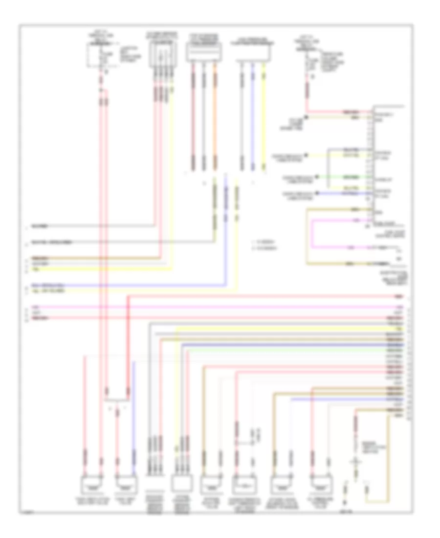
3.0L Turbo Hybrid, Engine Performance Wiring Diagram (1 of 8) for BMW ActiveHybrid 5 2013

List of elements for 3.0L Turbo Hybrid, Engine Performance Wiring Diagram (1 of 8) for BMW ActiveHybrid 5 2013:
- (right side of engine) knock sensor
- 1-3
- 4-6
- Act activation
- Bsd bus sig
- Bsd sig
- Coolant pump
- Cooling fans system
- Crankshaft position sensor (left rear side of engine)
- Digital motor electronics (dme) control module (right rear engine compt)
- Elec throttle act gnd
- Elec throttle act sig
- Electromotive throttle actuator
- Exhaust vanos solenoid valve (front of engine)
- Intake air temperature pressure sensor (right side of engine)
- Intake manifold pressure sensor (right side of engine)
- Knock sens sig
- Nca
- Oil level sensor
- Oxygen sensor before catalytic converter
- Quantity control valve
- Sens gnd
- Sens sig
- Sens sply
- Sply
- Vlv activation
- Vlv sply
- Wastegate valve pressure converter
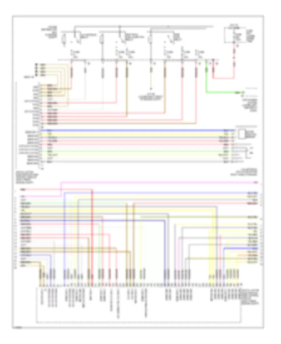
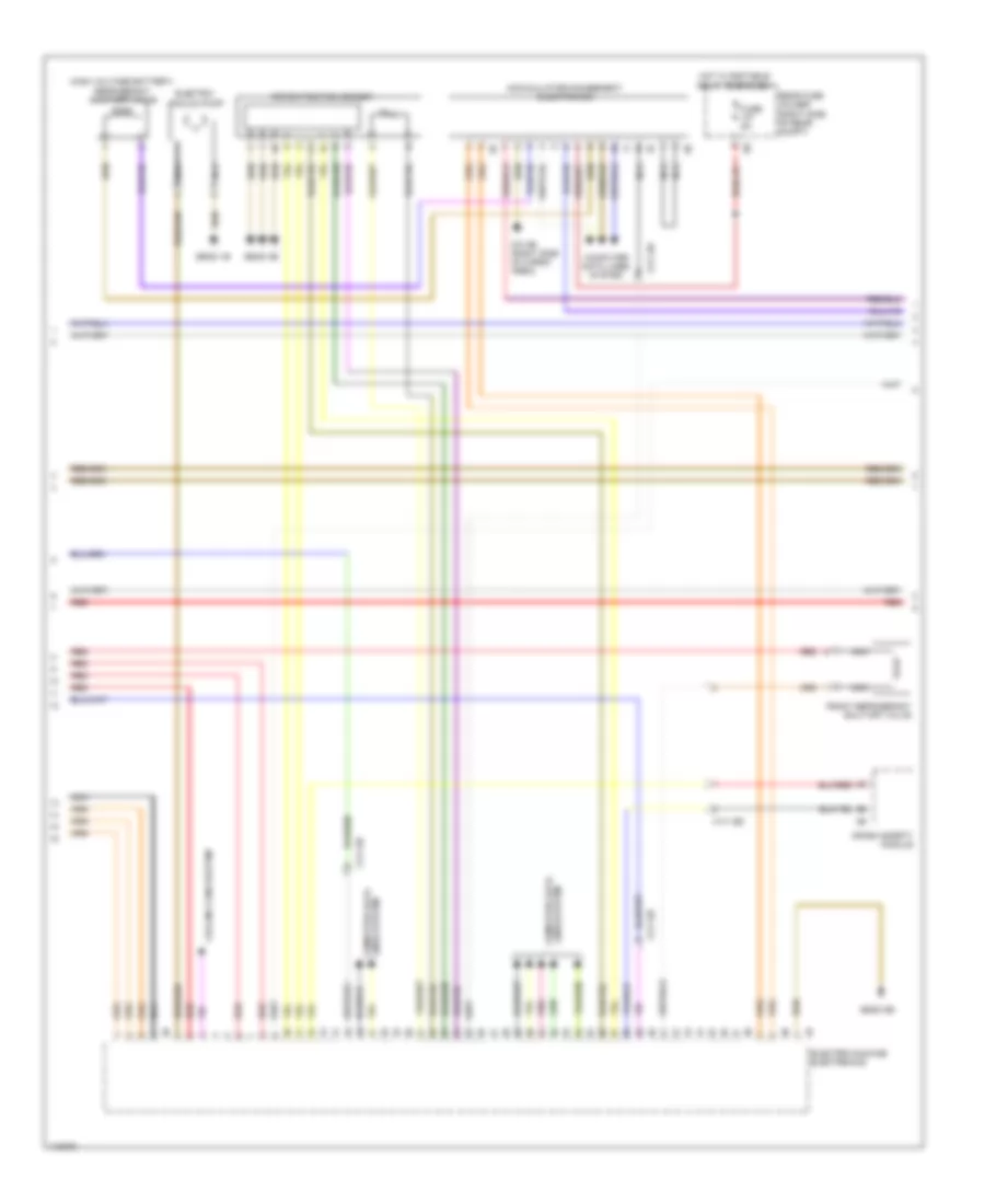
3.0L Turbo Hybrid, Engine Performance Wiring Diagram (2 of 8) for BMW ActiveHybrid 5 2013
List of elements for 3.0L Turbo Hybrid, Engine Performance Wiring Diagram (2 of 8) for BMW ActiveHybrid 5 2013:
- (top of engine) low pressure fuel sensor
- Bypass blow off valve
- Can bus
- Characteristic map thermostat (left front of engine)
- Computer data lines system
- Electric fuel pump (below right rear seat)
- Engine ventilation heating
- Exhaust camshaft sensor (rear of engine)
- Fuel pump
- Fuel pump control (ekps)
- Fuse 20a
- Fuse 5a
- Gnd
- High pressure pump position sensor
- Hot w/ terminal 30b relay energized
- Intake camshaft sensor (rear of engine)
- Intake vanos solenoid valve (front of engine)
- Junction box (right side of dash)
- Nca
- Oil pressure control valve
- Oxygen sensor after catalytic converter
- Pt can
- Pwr sply
- Rear fuse holder (right side of rear compt)
- Red
- Tank vent valve
- Tank ventilation shut-off valve
- W/ bosch
- W/o bosch
- Wake up
- X705 1b
- Z10 16b (under spare tire)
- Z23 1b
3.0L Turbo Hybrid, Engine Performance Wiring Diagram (3 of 8) for BMW ActiveHybrid 5 2013
List of elements for 3.0L Turbo Hybrid, Engine Performance Wiring Diagram (3 of 8) for BMW ActiveHybrid 5 2013:
- Activation
- Car access system (lower left center of dash)
- Digital motor electronics (dme) control module (right rear engine compt)
- Diverter vlv sply
- Dme main relay
- Fuse 100a
- Fuse 15a
- Fuse 20a
- Fuse 40a
- Fuse box (under spare tire)
- Gnd
- Heater sply
- Hot at all times
- Ignition & fuel injection relay
- Map activation
- Map sply
- Meter gnd
- Meter sig
- Meter sply
- Motor position sensor
- Mtr activation
- Oil press ctrl vlv sply
- Power distribution box (in engine compt)
- Pwr
- Red
- Sens gnd
- Sens sig
- Sens sply
- Valvetronic actuator motor (right side of engine)
- Valvetronic relay
- Ventilation activation
- Vlv activation
- Vlv sply
- Z10 3b (lower right front of engine compt)
- Z6000 1b
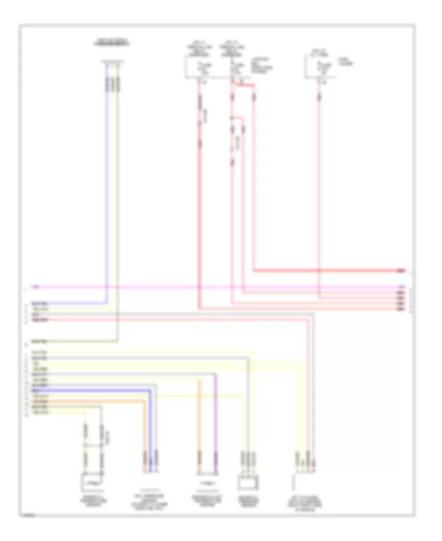
3.0L Turbo Hybrid, Engine Performance Wiring Diagram (4 of 8) for BMW ActiveHybrid 5 2013
List of elements for 3.0L Turbo Hybrid, Engine Performance Wiring Diagram (4 of 8) for BMW ActiveHybrid 5 2013:
- Engine coolant temperature sensor
- Engine oil pressure sensor
- Engine oil temperature sensor
- Fuse 10a
- Fuse 40a
- Fuse 5a
- Fuse holder
- Hot at all times
- Hot film mass air flow sensor (right front side of engine)
- Hot w/ terminal 30b relay energized
- Junction box (right side of dash)
- Rail pressure sensor (on right cylinder head fuel rail)
- Red
- Venturi nozzle pressure sensor
- X13 12b
- X13 13b
- X704 1b
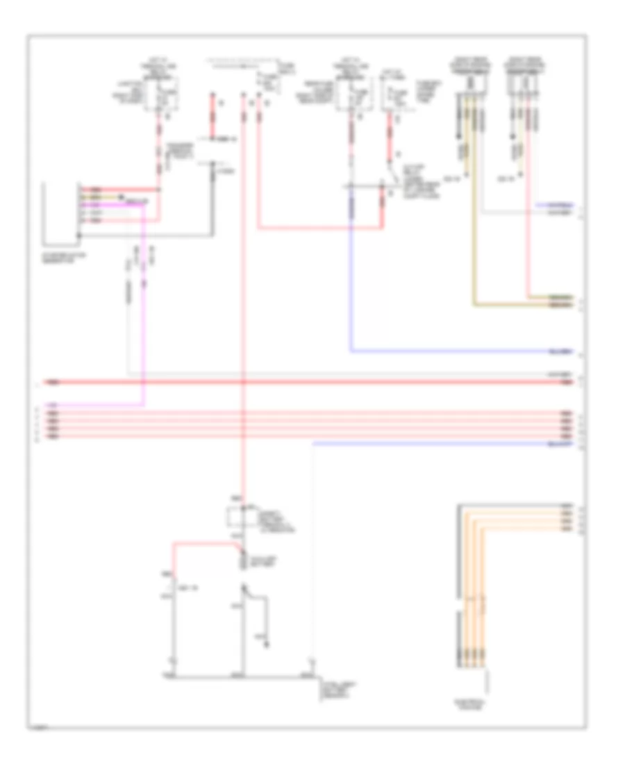
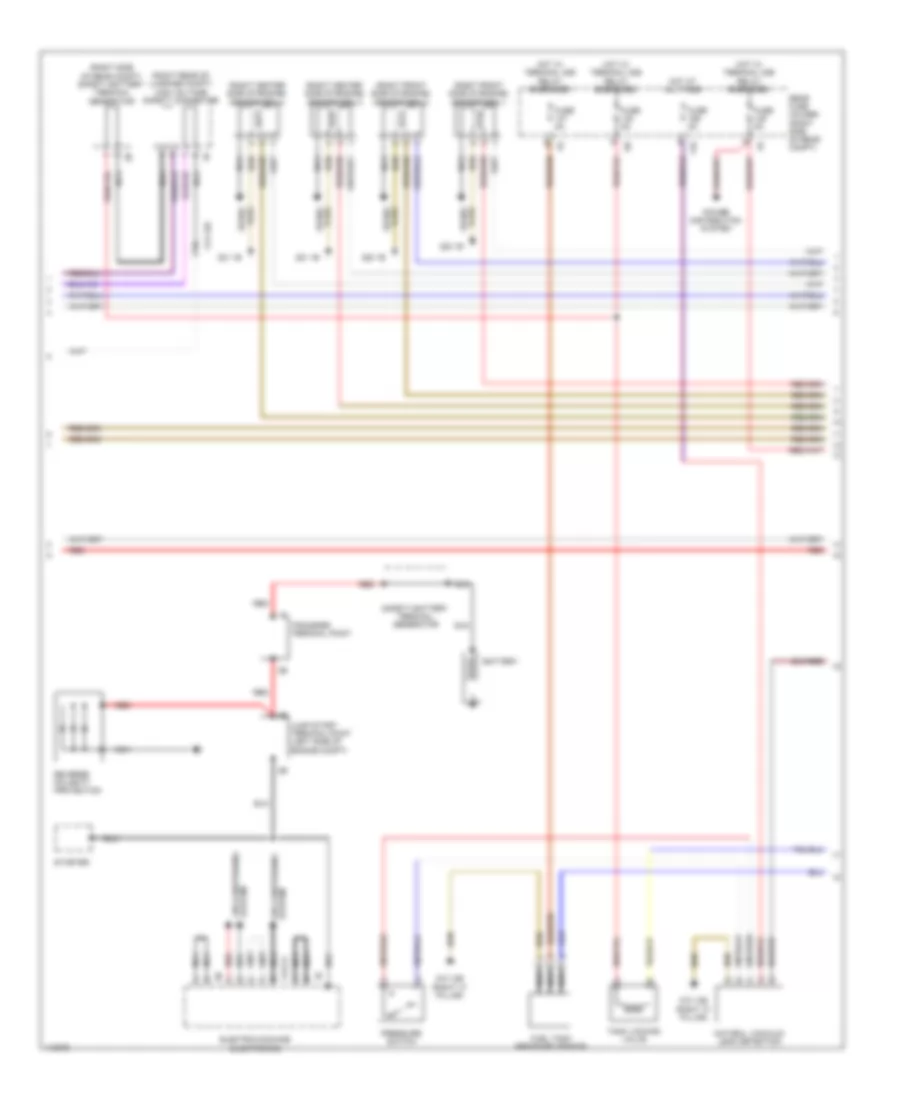
3.0L Turbo Hybrid, Engine Performance Wiring Diagram (5 of 8) for BMW ActiveHybrid 5 2013
List of elements for 3.0L Turbo Hybrid, Engine Performance Wiring Diagram (5 of 8) for BMW ActiveHybrid 5 2013:
- (right rear side of engine) ignition coil 5
- (right rear side of engine) ignition coil 6
- 11b
- Auxiliary battery
- Cut-off relay (under center rear of luggage compt floor)
- Electrical machine
- Fuse 100a
- Fuse 125a
- Fuse 5a
- Fuse box (under spare tire)
- Fuse box 2
- Hot at all times
- Hot w/ terminal 30b relay energized
- Intelligent battery sensor 2
- Junction box (right side of dash)
- Nca
- Plug spark
- Rear fuse holder (right side of rear compt)
- Red
- Safety battery terminal 2 alternator
- Spark plug
- Starter motor generator
- Transfer terminal point 3
- X10885
- X13 10b
- X593 1b
- X601 1b
- X671 3b
- Z22 1b
- Z6000 2b
3.0L Turbo Hybrid, Engine Performance Wiring Diagram (6 of 8) for BMW ActiveHybrid 5 2013
List of elements for 3.0L Turbo Hybrid, Engine Performance Wiring Diagram (6 of 8) for BMW ActiveHybrid 5 2013:
- (high voltage battery) refrigerant shut-off valve
- Accumulator-management electronics
- Computer data lines system
- Cooling fans system
- Crash safety module
- Electric vacuum pump
- Electric-machine electronics
- Front refrigerant shut-off valve
- Fuse 5a
- Hot w/ bistable relay energized
- Lines system computer data
- Nca
- Pnk
- Rear fuse holder (right side of rear compt)
- Red
- Rotor position sensor
- X13 12b
- Z10 8b (right side of cargo area)
- Z6000 1b
- Z6000 3b
- Z6000 5b
3.0L Turbo Hybrid, Engine Performance Wiring Diagram (7 of 8) for BMW ActiveHybrid 5 2013
List of elements for 3.0L Turbo Hybrid, Engine Performance Wiring Diagram (7 of 8) for BMW ActiveHybrid 5 2013:
- (right "c" pillar)
- (right center side of engine) ignition coil 3
- (right center side of engine) ignition coil 4
- (right front side of engine) ignition coil 1
- (right front side of engine) ignition coil 2
- (right rear of luggage compt) high voltage safety connector
- (right side of rear compt) safety battery terminal generator
- 11b
- Air conditioning system
- Battery
- Electric-machine electronics
- Fuel tank pressure sensor
- Fuse 5a
- Hot at all times
- Hot w/ terminal 30b relay energized
- Jump start terminal point (left side of engine compt)
- Natural vaccuum leak detection
- Nca
- Plug spark
- Power distribution system
- Pressure switch
- Rear fuse holder (right side of rear compt)
- Red
- Reverse polarity protection
- Safety battery terminal generator
- Spark plug
- Starter
- System air conditioning
- Tank locking valve
- Transfer terminal point
- X13 12b
- X14741
- Z10 13b
- Z20 1b
- Z21 1b
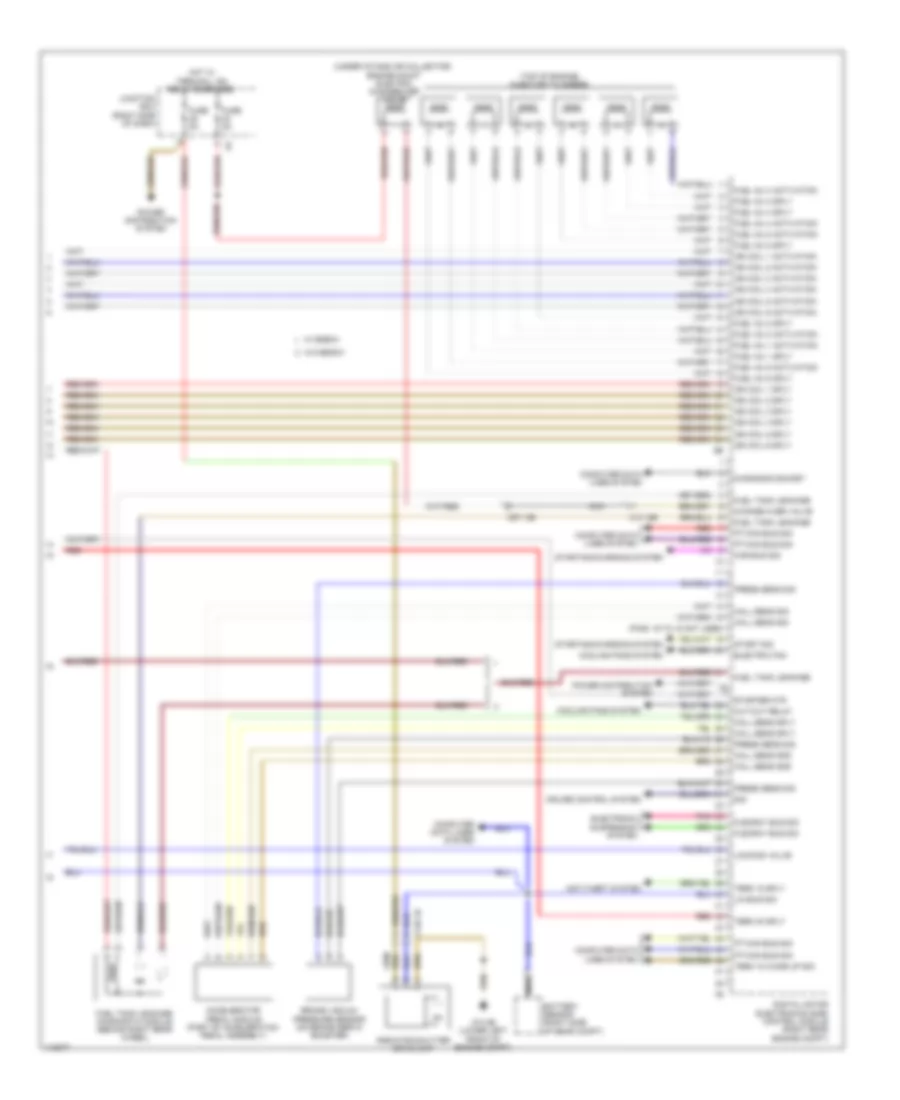
3.0L Turbo Hybrid, Engine Performance Wiring Diagram (8 of 8) for BMW ActiveHybrid 5 2013
List of elements for 3.0L Turbo Hybrid, Engine Performance Wiring Diagram (8 of 8) for BMW ActiveHybrid 5 2013:
- (pins: 16 to 18 not used)
- (top of engine) injector cylinders
- (under intake air collector) engine mount electric changeover valve
- Accelerator pedal module (part of acceleration pedal assembly)
- Anti-theft system
- Battery sensor (right side of rear compt)
- Brake vacuum pressure sensor (on brake servo booster)
- Car bus sig
- Change over valve
- Computer data lines system
- Cooling fans system
- Cruise control system
- Cut-out relay
- Diagnosis socket
- Digital motor electronics (dme) control module (right rear engine compt)
- Electric fan
- Electronic suspension system
- Flexray bus sig
- Fuel inj 1 activation
- Fuel inj 1 sply
- Fuel inj 2 activation
- Fuel inj 2 sply
- Fuel inj 3 activation
- Fuel inj 3 sply
- Fuel inj 4 activation
- Fuel inj 4 sply
- Fuel inj 5 activation
- Fuel inj 5 sply
- Fuel inj 6 activation
- Fuel inj 6 sply
- Fuel tank leakage
- Fuel tank leakage diagnostic module (behind right rear wheel)
- Fuse 5a
- Hall sens gnd
- Hall sens sig
- Hall sens sply
- Hot w/ terminal 15n relay energized
- Ign coil 1 activation
- Ign coil 1 sply
- Ign coil 2 activation
- Ign coil 2 sply
- Ign coil 3 activation
- Ign coil 3 sply
- Ign coil 4 activation
- Ign coil 4 sply
- Ign coil 5 activation
- Ign coil 5 sply
- Ign coil 6 activation
- Ign coil 6 sply
- Junction box (right side of dash)
- Lin bus sig
- Locking valve
- Nca
- Pnk
- Power distribution system
- Press sens sig
- Pt-can bus sig
- Radiator shutter drive unit
- Red
- Sig
- Start sig
- Starter mtr
- Starting/charging system
- Term 15 sply
- Term 15 wake up sig
- Term 30 sply
- W/ bosch
- W/o bosch
- X13 12b
- X148 1b
- X671 3b
- Z10 2b (lower left front of engine compt)