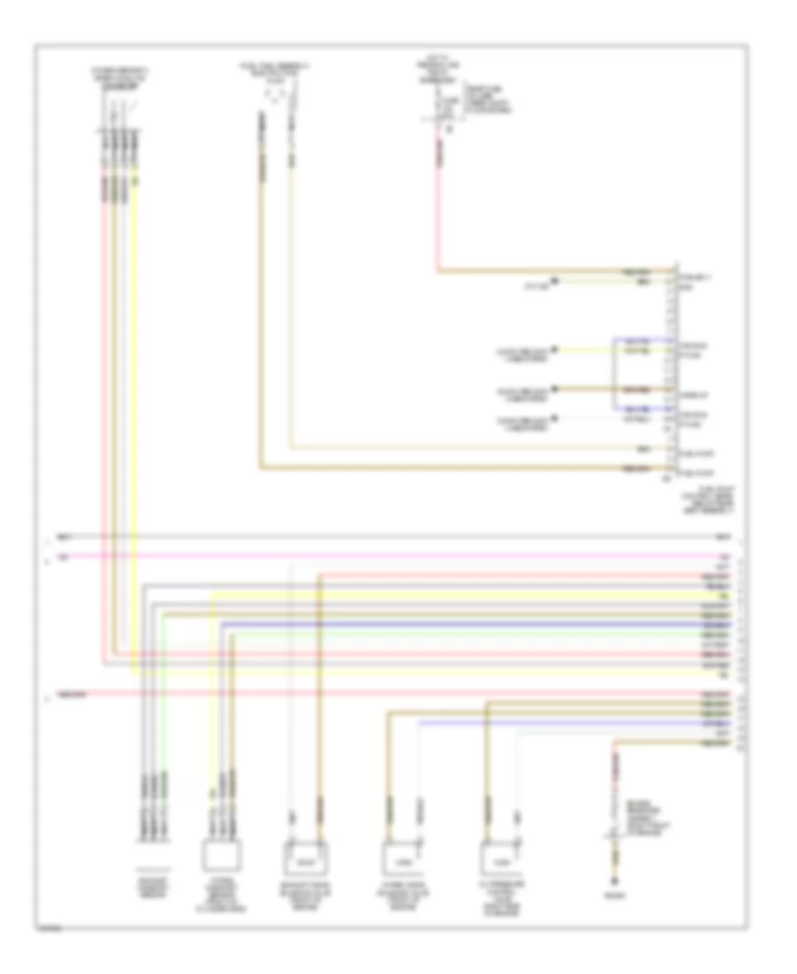
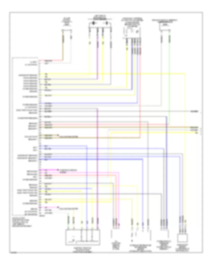
ENGINE PERFORMANCE
3.0L
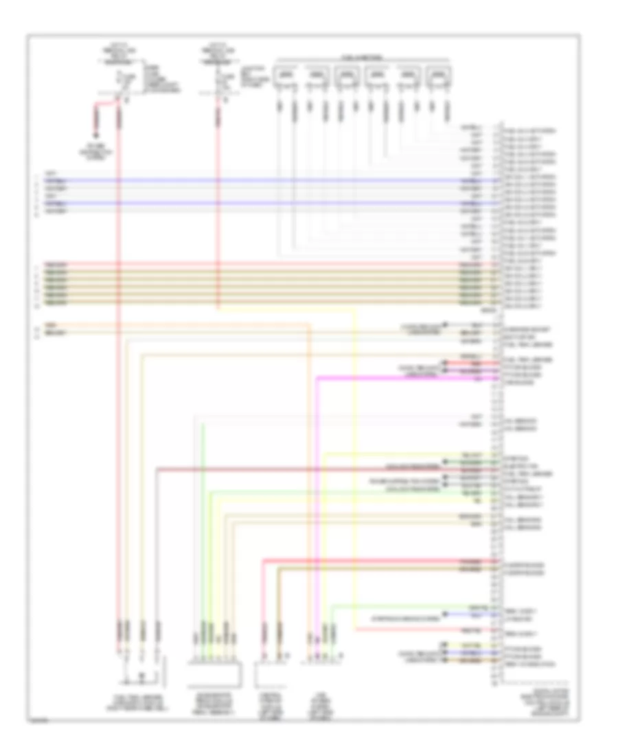
3.0L, Engine Performance Wiring Diagram (1 of 5) for BMW X3 35i 2011

List of elements for 3.0L, Engine Performance Wiring Diagram (1 of 5) for BMW X3 35i 2011:
- (center of intake manifold)
- (center of intake manifold) disa servo motor 1
- (intake tube assembly)
- (left side of engine block) knock sensor
- Bsd bus sig
- Charcoal filter valve
- Crankshaft sens gnd
- Crankshaft sens sig
- Crankshaft sens sply
- Crankshaft sensor (lower rear of engine block)
- Cylinder 1-3
- Cylinder 4-6
- Digital motor electronics (dme) control module
- Disa act
- Disa gnd
- Disa servo motor 2
- Disa sply
- Elec throttle act gnd
- Elec throttle act sig
- Elec throttle act sply
- Elec throttle vlv act
- Electric-throttle valve actuator (throttle valve assembly)
- Filter valve sply
- Gnd
- Hot-film air mass meter (intake tube assembly)
- Intake manifold pressure sensor
- Knock sens sig
- Nca
- Oil condition sensor (base of oil pan)
- Sens gnd
- Sens sig
- Sens sply
- Sig
- Starting/charging system
- Temp sens sig
- X60002
3.0L, Engine Performance Wiring Diagram (2 of 5) for BMW X3 35i 2011
List of elements for 3.0L, Engine Performance Wiring Diagram (2 of 5) for BMW X3 35i 2011:
- (fuel tank assembly) electric fuel pump
- Can bus
- Computer data lines system
- Engine breather heater 1 (right front of engine)
- Exhaust camshaft sensor
- Exhaust vanos solenoid valve (front of engine)
- Fuel pump
- Fuel pump control (ekps) (below rear seat assembly)
- Fuse 20a
- Gnd
- Hot w/ terminal 30b relay energized
- Intake camshaft sensor (front of cylinder head)
- Intake vanos solenoid valve (front of engine)
- Nca
- Oil pressure control valve (right side of engine)
- Oxygen sensor 2 after catalytic converter
- Pt can
- Pwr sply
- Rear fuse holder (rear compt floor board)
- Wake-up
- X64553
- Z10 12b
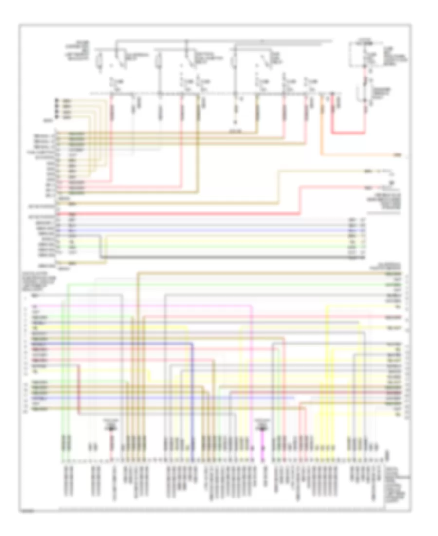
3.0L, Engine Performance Wiring Diagram (3 of 5) for BMW X3 35i 2011
List of elements for 3.0L, Engine Performance Wiring Diagram (3 of 5) for BMW X3 35i 2011:
- Act activation
- Activation
- Bsd bus sig
- Coolant pump sply
- Cooling fans system
- Ctrl vlv acti
- Ctrl vlv sply
- Digital motor electronics (dme) control module (left rear of eng compt)
- Digital motor electronics (dme) control module (left rear of engine compt)
- Dme main relay
- Fuel injection
- Fuse 100a
- Fuse 15a
- Fuse 20a
- Fuse 40a
- Fuse box (right rear compt floor board)
- Gnd
- Heater sply
- Hot at all times
- Ignition & fuel injection relay
- Map acti
- Map sply
- Nca
- Oxygen sens gnd
- Oxygen sens sig
- Oxygen sens sply
- Power distribution box (left rear of eng compt)
- Red
- Sens engi sply
- Sens gnd
- Sens sig
- Sens sply
- Shield
- Solenoid vlv sply
- Sply
- Temp sens sig
- Terminal 15
- Transfer terminal point
- Valvetronic position sensor
- Valvetronic relay
- Vanos solenoid vlv
- Variable valve gear servo meter (right side of engine)
- X60003
- X60004
- X60005
- X60181
- X60182
- X60189
- X6454
- Z10 1b
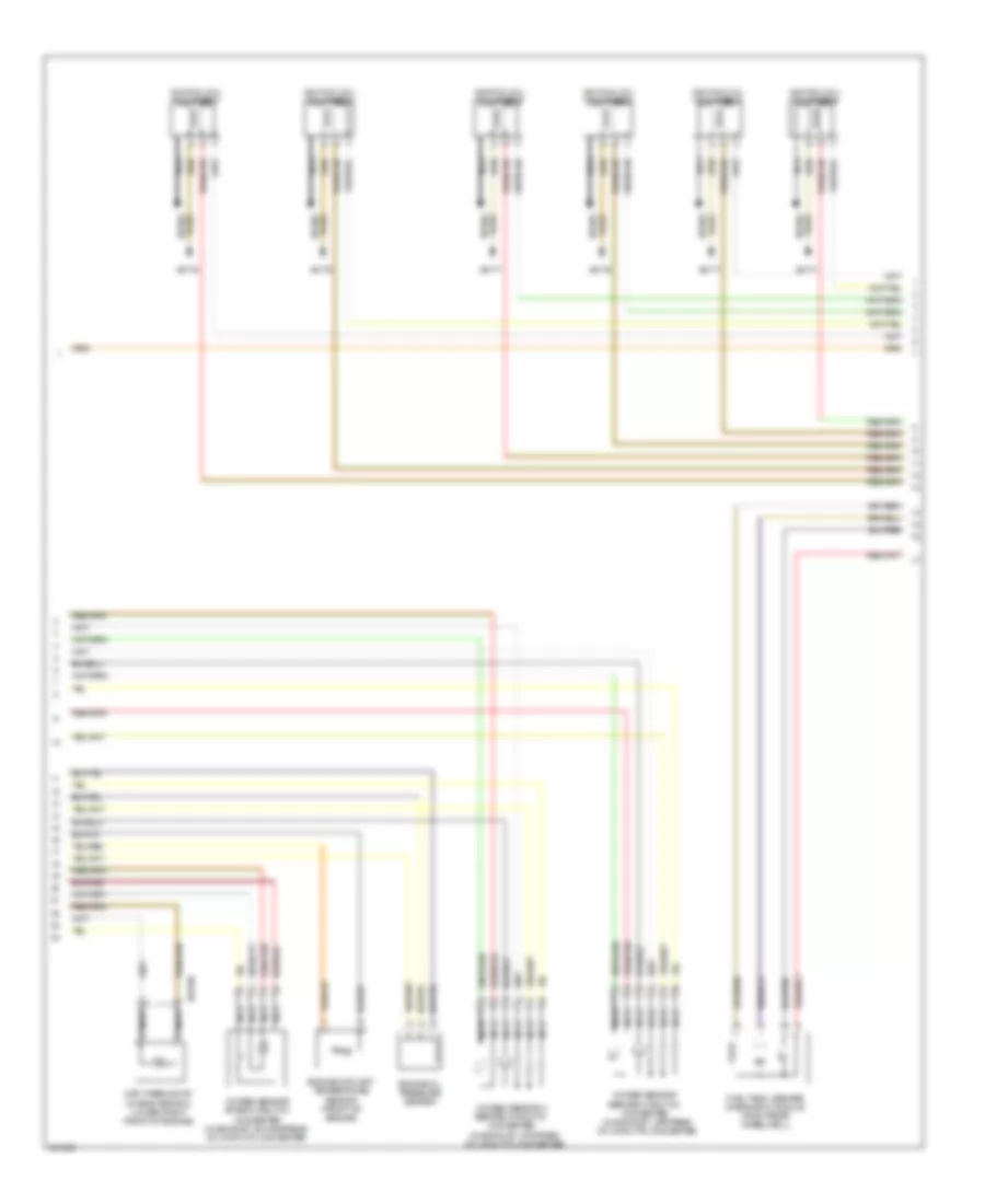
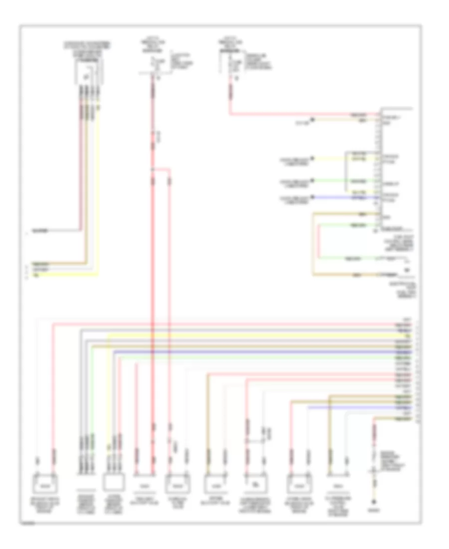
3.0L, Engine Performance Wiring Diagram (4 of 5) for BMW X3 35i 2011
List of elements for 3.0L, Engine Performance Wiring Diagram (4 of 5) for BMW X3 35i 2011:
- (in exhaust, upstream of catalytic converter
- Engine coolant temperature sensor (front of engine)
- Engine oil pressure sensor
- Fuel tank leakage diagnostic module (right rear wheelwell)
- Ignition coil cylinder 1
- Ignition coil cylinder 2
- Ignition coil cylinder 3
- Ignition coil cylinder 4
- Ignition coil cylinder 5
- Ignition coil cylinder 6
- Map thermostat characteristic (lower right front of engine)
- Nca
- Oxygen sensor 2 before catalytic converter
- Oxygen sensor after catalytic converter (in exhaust, downstream of catalytic converter
- Oxygen sensor before catalytic converter (in exhaust, upstream of catalytic converter
- Plug spark
- Spark plug
- X6176
- X6177
- X62790
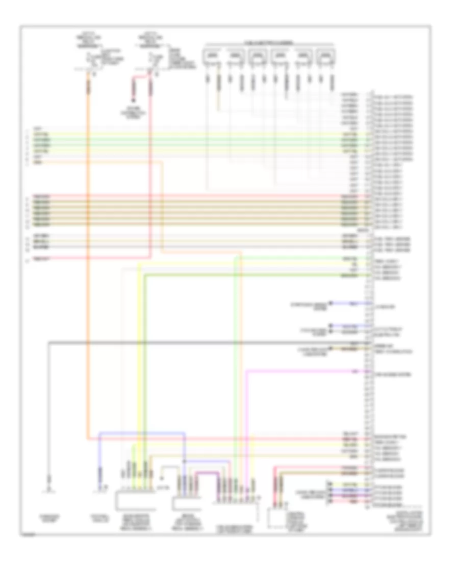
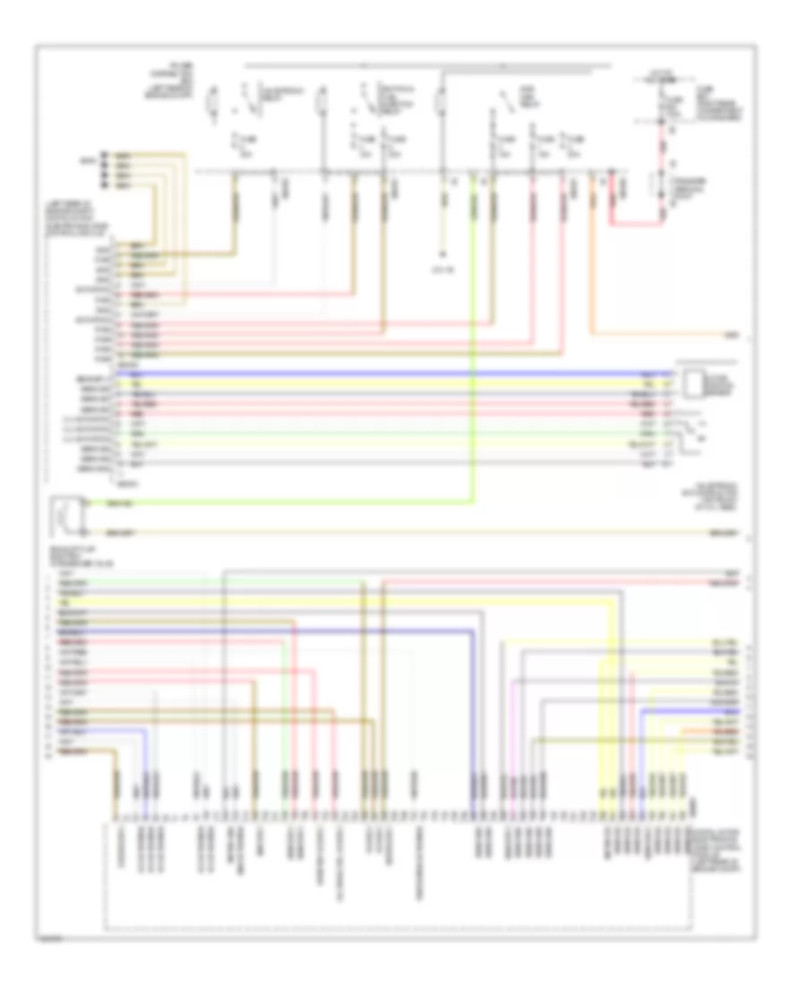
3.0L, Engine Performance Wiring Diagram (5 of 5) for BMW X3 35i 2011
List of elements for 3.0L, Engine Performance Wiring Diagram (5 of 5) for BMW X3 35i 2011:
- Accelerator pedal module (accelerator pedal assembly)
- Brake light switch (top of brake pedal assembly)
- Car access system
- Car access system (left side of dash)
- Central gateway module (left side of dash)
- Computer data lines system
- Cooling fans system
- Cut-out relay
- Diagnosis socket
- Digital motor electronics (dme) control module (left rear of engine compt)
- Electric fan
- Engine start sig
- Flexray bus sig
- Footwell module
- Fuel inj 1 activation
- Fuel inj 1 sply
- Fuel inj 2 activation
- Fuel inj 2 sply
- Fuel inj 3 activation
- Fuel inj 3 sply
- Fuel inj 4 activation
- Fuel inj 4 sply
- Fuel inj 5 activation
- Fuel inj 5 sply
- Fuel inj 6 activation
- Fuel inj 6 sply
- Fuel injector cylinders
- Fuel tank leakage
- Fuse 15a
- Fuse 5a
- Hal sens gnd
- Hal sens sig
- Hal sens sply
- Hot w/ terminal 30b relay energized
- Ign coil 1 activation
- Ign coil 1 sply
- Ign coil 2 activation
- Ign coil 2 sply
- Ign coil 3 activation
- Ign coil 3 sply
- Ign coil 4 activation
- Ign coil 4 sply
- Ign coil 5 activation
- Ign coil 5 sply
- Ign coil 6 activation
- Ign coil 6 sply
- Junction box (right side of dash)
- Lin bus sig
- Pnk/red
- Power distribution system
- Pt-can bus sig
- Rear fuse holder (rear compt floor board)
- Red
- Speed sig
- Starting/charging system
- Term 15 sply
- Term 15 wake up sig
- Term 30 sply
- X60006
- Z10 7b
3.0L TWIN TURBO
3.0L Twin Turbo, Engine Performance Wiring Diagram (1 of 5) for BMW X3 35i 2011
List of elements for 3.0L Twin Turbo, Engine Performance Wiring Diagram (1 of 5) for BMW X3 35i 2011:
- (exhaust manifold assembly) wastegate valve
- (in exhaust, upstream of catalytic converter) oxygen sensor before catalytic converter
- (left side of engine block) knock sensor
- Act activation
- Bsd bus sig
- Bsd sig
- Coolant pump
- Cooling fans system
- Crankshaft sens gnd
- Crankshaft sens sig
- Crankshaft sens sply
- Crankshaft sensor (lower rear of engine block)
- Digital motor electronics (dme) control module (left rear of engine compartment)
- Elec throttle act gnd
- Elec throttle act sig
- Electric throttle valve actuator (throttle valve assy)
- Intake air temperature/ air pressure sensor (intake air tube ducting)
- Intake manifold pressure sensor (intake manifold assembly)
- Intake pipe pres sens
- Knock sens sig
- Nca
- Oil condition sensor base of oil pan)
- Oxygen sens sig
- Sens gnd
- Sens sig
- Sens sply
- Sply
- Starting/charging system
- Vlv activation
- Vlv sply
- Volume control valve
- X60002
3.0L Twin Turbo, Engine Performance Wiring Diagram (2 of 5) for BMW X3 35i 2011
List of elements for 3.0L Twin Turbo, Engine Performance Wiring Diagram (2 of 5) for BMW X3 35i 2011:
- (in exhaust, downstream of catalytic converter) oxygen sensor after catalytic converter
- Bypass blow-off valve
- Can bus
- Characteristic map thermostat (lower right front of engine)
- Charcoal filter valve
- Computer data lines system
- Electric fuel pump (fuel tank assembly)
- Engine breather heater 1 (right front of engine)
- Exhaust camshaft sensor (front of cyl head)
- Exhaust vanos solenoid valve (front of engine)
- Fuel pump
- Fuel pump control (ekps) (below rear seat assembly)
- Fuse 20a
- Fuse 5a
- Gnd
- Hot w/ terminal 30b relay energized
- Intake camshaft sensor (front of cyl head)
- Intake vanos solenoid valve (front of engine)
- Junction box (right side of dash)
- Nca
- Oil pressure control valve (right side of engine)
- Pt can
- Pwr sply
- Rear fuse holder (rear compt floor board)
- Red
- Tank vent shut-off valve
- Wake-up
- X13 1b
- X60572
- X62790
- X64553
- Z10 12b
3.0L Twin Turbo, Engine Performance Wiring Diagram (3 of 5) for BMW X3 35i 2011
List of elements for 3.0L Twin Turbo, Engine Performance Wiring Diagram (3 of 5) for BMW X3 35i 2011:
- (left rear of engine compt) digital motor electronics (dme) control module
- Activation
- Digital motor electronics (dme) control module (left rear of engine compt)
- Diverter vlv sply
- Dme main relay
- Exhaust flap electric changeover valve
- Fuse 100a
- Fuse 15a
- Fuse 20a
- Fuse 40a
- Fuse box (right rear compartment floor board)
- Gnd
- Heater sply
- Hot at all times
- Ignition & fuel injection relay
- Map activation
- Map sply
- Meter gnd
- Meter sig
- Meter sply
- Motor position sensor
- Oil pres ctrl vlv sply
- Power distribution box (left rear of engine compt)
- Pwr
- Red
- Sens gnd
- Sens sig
- Sens sply
- Transfer terminal point
- Valvetronic actuator motor (top front of cyl head)
- Valvetronic relay
- Ventilation activation
- Vlv activation
- Vlv sply
- X60003
- X60004
- X60005
- X60181
- X60182
- X60189
- X6454
- Z10 1b
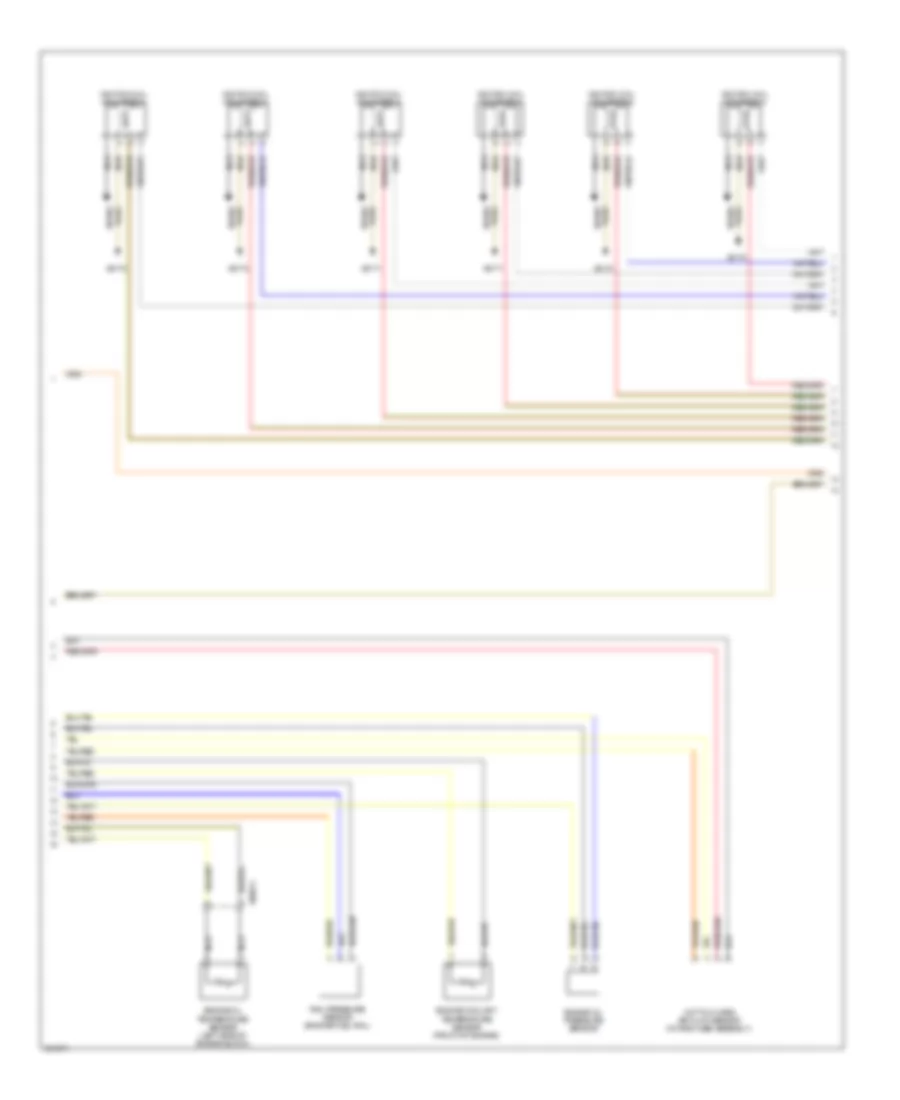
3.0L Twin Turbo, Engine Performance Wiring Diagram (4 of 5) for BMW X3 35i 2011
List of elements for 3.0L Twin Turbo, Engine Performance Wiring Diagram (4 of 5) for BMW X3 35i 2011:
- Engine coolant temperature sensor (front of engine)
- Engine oil pressure sensor
- Engine oil temperature sensor (left side of engine block)
- Hot film mass air flow sensor (intake tube assembly)
- Ignition coil cylinder 1
- Ignition coil cylinder 2
- Ignition coil cylinder 3
- Ignition coil cylinder 4
- Ignition coil cylinder 5
- Ignition coil cylinder 6
- Nca
- Plug spark
- Rail pressure sensor (engine fuel rail)
- Spark plug
- X60574
- X6170
- X6171
- X6172
3.0L Twin Turbo, Engine Performance Wiring Diagram (5 of 5) for BMW X3 35i 2011
List of elements for 3.0L Twin Turbo, Engine Performance Wiring Diagram (5 of 5) for BMW X3 35i 2011:
- Accelerator pedal module (accelerator pedal assembly)
- Car access system (left side of dash)
- Car bus sig
- Central gateway module (left side of dash)
- Computer data lines system
- Cooling fans system
- Cut-out relay
- Diagnosis socket
- Digital motor electronics (dme) control module (left rear of engine compt)
- Electric fan
- Exh flap sig
- Flexray bus sig
- Fuel inj 1 activation
- Fuel inj 1 sply
- Fuel inj 2 activation
- Fuel inj 2 sply
- Fuel inj 3 activation
- Fuel inj 3 sply
- Fuel inj 4 activation
- Fuel inj 4 sply
- Fuel inj 5 activation
- Fuel inj 5 sply
- Fuel inj 6 activation
- Fuel inj 6 sply
- Fuel injectors
- Fuel tank leakage
- Fuel tank leakage diagnostic module (right rear wheelwell)
- Fuse 15a
- Fuse 5a
- Hal sens sig
- Hall sens gnd
- Hall sens sply
- Hot w/ terminal 30b relay energized
- Ign coil 1 activation
- Ign coil 1 sply
- Ign coil 2 activation
- Ign coil 2 sply
- Ign coil 3 activation
- Ign coil 3 sply
- Ign coil 4 activation
- Ign coil 4 sply
- Ign coil 5 activation
- Ign coil 5 sply
- Ign coil 6 activation
- Ign coil 6 sply
- Junction box (right side of dash)
- Lin bus sig
- Pnk/red
- Power distribution system
- Pt-can bus sig
- Rear fuse holder (rear compt floor board)
- Red
- Start sig
- Starting/charging system
- Term 15 sply
- Term 15 wake up sig
- Term 30 sply
- X60006