
SHIFT INTERLOCKS
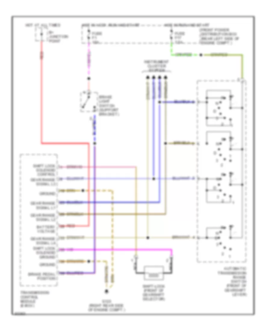
Shift Interlock Wiring Diagram for BMW 525i 1995
List of elements for Shift Interlock Wiring Diagram for BMW 525i 1995:
ANTI-LOCK BRAKESAIR CONDITIONINGENGINE PERFORMANCECRUISE CONTROLANTI-THEFTCOMPUTER DATA LINESCOOLING FANBODY COMPUTEREXTERIOR LIGHTSGROUND DISTRIBUTIONHORNINSTRUMENT CLUSTERDEFOGGERSINTERIOR LIGHTSPOWER DISTRIBUTIONMEMORY SYSTEMSHEADLIGHTSPOWER SEATSPOWER TOP/SUNROOFPOWER DOOR LOCKSPOWER WINDOWSPOWER MIRRORSSTARTING/CHARGINGWARNING SYSTEMSSUPPLEMENTAL RESTRAINTSTRANSMISSIONSHIFT INTERLOCKSRADIOWIPER/WASHER