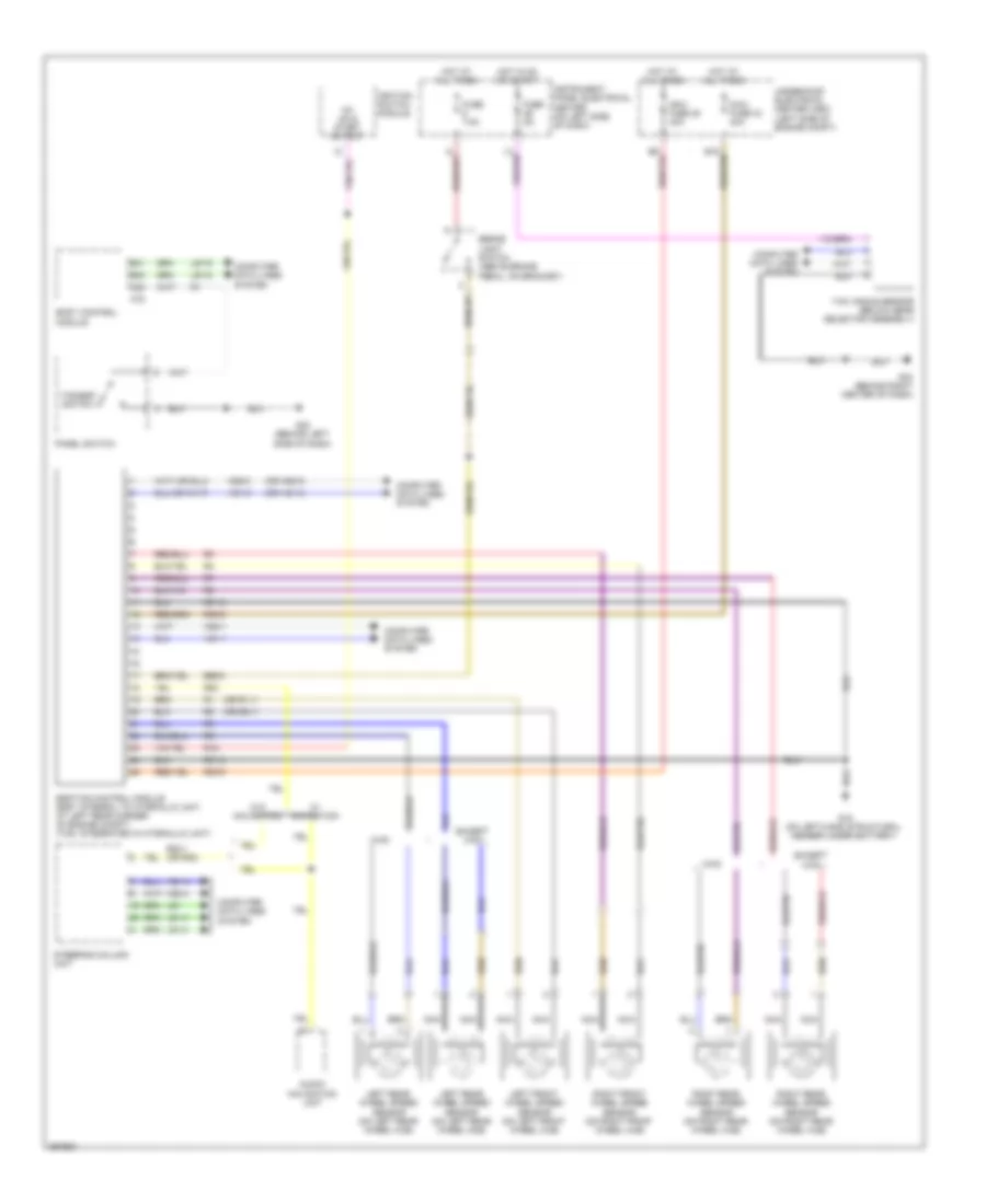
ANTI-LOCK BRAKES
Anti-lock Brakes Wiring Diagram for Saab 9-3 Aero 2008
List of elements for Anti-lock Brakes Wiring Diagram for Saab 9-3 Aero 2008:
- (or hs1-3)
- (or hs2-3)
- (or r1-1)
- (or r2-1)
- 15+ on & start output
- A23
- Audio/ navigation unit
- B40
- B41
- Body control module
- Brake light switch (above brake pedal, on bracket)
- Computer data lines system
- E65-2
- Esp/tcs control module (esp: integral to hydraulic unit, at left rear corner of engine compt) (tcs: integrated in hydraulic unit)
- Except xwd
- Fuse 5a
- Fuse 7.5a
- G15 (on left-hand structural member under battery)
- G40 (behind left side of dash)
- G43 (behind right center of dash)
- Hot at all times
- Hot in on or start
- Hs1-1
- Hs1-2
- Hs1-4
- Hs2-1
- Hs2-2
- Hs2-4
- Ignition switch module
- Instrument panel electrical center (on left side of dash)
- K78
- Left front wheel speed sensor (on left front wheel hub)
- Left rear wheel speed sensor (on left rear wheel hub)
- Ls1
- Ls1-3
- Ls1-4
- Ls1-5
- Ls1-9
- Maxi fuse 28 40a
- Maxi fuse 33 40a
- Nca
- Panel switch
- R15
- R20
- R20-1 (or r20)
- R30-5
- R30-6
- R31-5
- R31-6
- Right front wheel speed sensor (on right front wheel hub)
- Right rear wheel speed sensor (on right rear wheel hub)
- Steering column unit
- Tcs/esp switch
- Underhood electrical center (uec) (left side of engine compt)
- W/ navigation
- W/o navigation
- Xwd
- Yaw angle sensor (below gear selector assembly)
 English