ENGINE PERFORMANCE
2.3L
2.3L Turbo, Engine Performance Wiring Diagrams (1 of 2) for Saab 9000 CS 1997

List of elements for 2.3L Turbo, Engine Performance Wiring Diagrams (1 of 2) for Saab 9000 CS 1997:
- 1219a
- 136g
- 541a
- 541b
- 541c
- 541d
- 541e
- 541e-1
- 549c
- 551a
- 572c-1
- 700-1
- 713a
- 740b
- 896a
- A/t
- A/t w/ anti-theft
- Boost pressure control valve (on radiator fan cowl)
- Brake light switch (on brake pedal support)
- D14
- Dashboard electrical distribution box (behind glove compartment)
- Distri- bution terminal
- Electronic display unit
- Evap canister purge valve (right front side of engine compartment)
- Front heated oxygen sensor (front of catalytic converter)
- Fuse 10a
- Fuse 15a
- Fuse 5a
- G112 (left side of engine bracket)
- G112 (on left side engine) bracket)
- Hot
- Hot at all times
- Ignition discharge module (left side of fire wall)
- In run
- Injector
- Instrument cluster
- M/t
- Main relay
- Manifold absolute pressure sensor (on fire wall)
- Red
- Reversing light switch
- Reversing lights relay
- Selector lever position switch
- Spark plug connectors
- Trionic engine control module (left side of firewall)
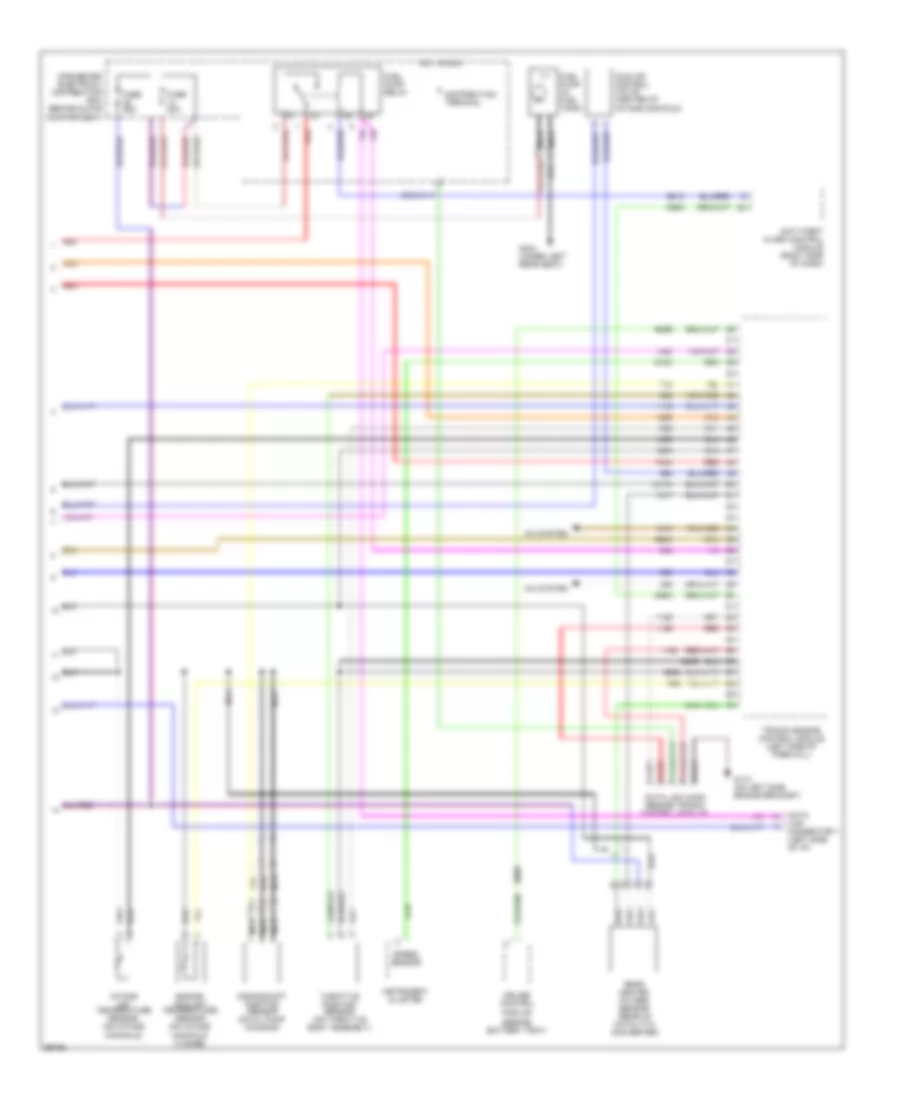
2.3L Turbo, Engine Performance Wiring Diagrams (2 of 2) for Saab 9000 CS 1997
List of elements for 2.3L Turbo, Engine Performance Wiring Diagrams (2 of 2) for Saab 9000 CS 1997:
- (beside battery tray)
- 1217a
- 546a
- 555b
- 555c
- 561c
- 608b
- 613c
- 688a
- 740a
- A/c system
- Anti-theft alarm control module (right side of dash)
- Crankshaft position sensor (on oil pump housing)
- Cruise control
- Dashboard electrical distribution box (behind glove compartment)
- Data link conn (beside trionic control module)
- Data link connector 1 (left side of i/p)
- Distribution terminal
- Engine coolant temperature sensor (on intake manifold flange)
- Fuel pump (in fuel tank)
- Fuel pump relay
- Fuse 20a
- Fuse 25a
- G112 (on left side engine bracket)
- G304 (under left rear seat)
- Hot in run
- Idle air control valve (center of intake manifold)
- Instrument cluster
- Intake air temperature sensor (on intake manifold)
- Module
- Nca
- Rear heated oxygen sensor (rear of catalytic converter)
- Red
- Speed sensor
- Throttle position sensor (on throttle body assembly)
- Trionic engine control module (left side of firewall)
3.0L
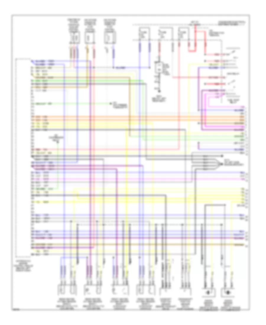
3.0L, Engine Performance Wiring Diagrams (1 of 2) for Saab 9000 CS 1997
List of elements for 3.0L, Engine Performance Wiring Diagrams (1 of 2) for Saab 9000 CS 1997:
- (center of intake manifold) idle air control valve
- (front of engine cylinder block)
- (on intake manifold) inner vim flap control valve
- (on intake manifold) outer vim flap control valve
- +30 distribution terminal
- 1204a
- 1222b
- 1310b
- 1321a
- 1321b
- 1322a
- 541a
- 541b
- 541c
- 541d
- 541e
- 541f
- 541g
- 561h
- 561k
- 642a
- A/c anti-freeze thermostat
- A/c compressor relay
- Camshaft position sensor (beside camshaft drive)
- Crankshaft position sensor (on oil pump housing)
- Dashbaord electrical distribution box
- Front heated oxygen sensor, bank 1 (in exhaust manifold)
- Front heated oxygen sensor, bank 2 (in exhaust manifold)
- Fuel pump (in fuel tank)
- Fuel pump relay
- Fuse 20a
- Fuse 25a
- Fuse 5a
- G112 (of left side engine bracket)
- G304 (below left rear seat)
- Hot at all times
- Knock sensor, bank 1
- Knock sensor, bank 2 (rear of engine cylinder block)
- Main relay
- Motronic 5.2 engine control module (behind left side of dash)
- Nca
- Rear heated oxygen sensor, bank 1 (behind catalytic converter)
- Rear heated oxygen sensor, bank 2 (behind catalytic converter)
- Red
- Splice
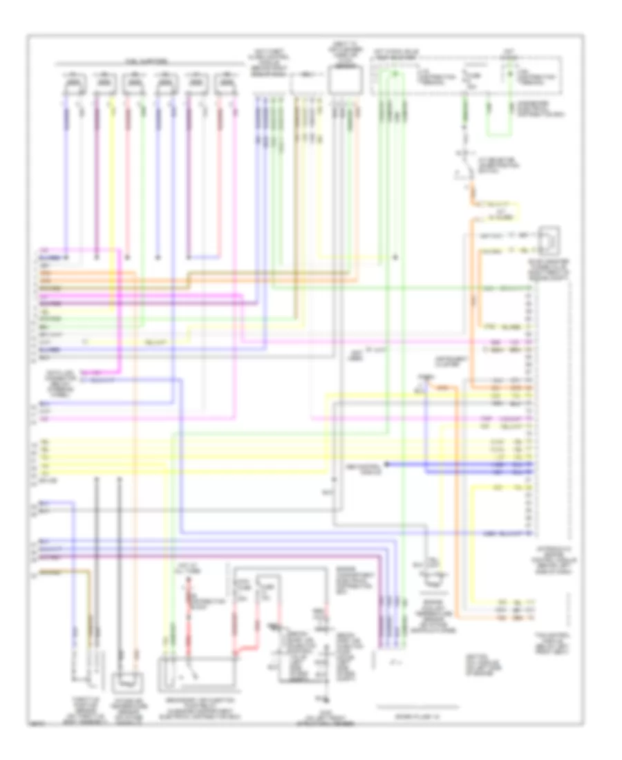
3.0L, Engine Performance Wiring Diagrams (2 of 2) for Saab 9000 CS 1997
List of elements for 3.0L, Engine Performance Wiring Diagrams (2 of 2) for Saab 9000 CS 1997:
- (next to air cleaner) mass air flow sensor
- (not used)
- +15 distribution terminal
- +54 distribution terminal
- +b distribution red block
- 1102b
- 1310a
- 1310c
- 546a
- 546a-1
- 561b
- 572c
- 688a
- 896a
- A/t selector lever position switch
- A/t w/ alarm
- Abs control module
- Anti-theft alarm control module (behind right side of dash)
- Dashboard electrical distribution box
- Data link connector (below steering wheel)
- Edu
- Engine compartment electrical distribution box
- Engine coolant temperature sensor (on intake manifold flange)
- Evap canister purge valve (right front of engine compt)
- Fuel injectors
- Fuse 10a
- Fuse 30a
- G100 (on left front structural member)
- Hot at all times
- Hot in run
- Hot in run, bulb test or start
- Ignition coil module (on left side of engine)
- Instrument cluster
- Intake air temperature sensor (on intake manifold)
- Maxi fuse 30a
- Motronic 5.2 engine control module (behind left side of dash)
- Nca
- Red
- Secon- dary air injection control valve (left side of eng compt)
- Secon- dary air injection pump motor (left side of eng compt)
- Secondary air injection pump relay (in engine compartment electrical distribution box)
- Spark plugs 1-6
- Splice
- Tach
- Tcs control module (below left front seat)
- Throttle position sensor (on throttle body assembly)