ENGINE PERFORMANCE
3.6L VIN 7
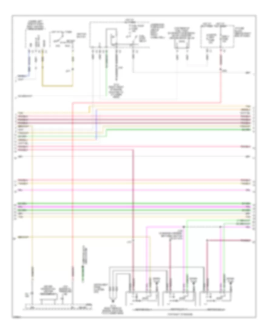
3.6L VIN 7, Engine Performance Wiring Diagram (1 of 5) for Saturn Outlook XE 2008

List of elements for 3.6L VIN 7, Engine Performance Wiring Diagram (1 of 5) for Saturn Outlook XE 2008:
- 5v ref 1
- 5v ref 2
- A/c cmprsr clutch relay
- Accelerator pedal position (app) sensor (above accelerator pedal)
- Air conditioning system
- App sen 1 sig
- App sens 2 sig
- Bank 1 sens 1 sig
- Bank 1 sens 2 sig
- Cam phaser 2 ctrl
- Cam phaser 4 ctrl
- Clutch rly ctrl
- Cooling fan rly ctrl
- Cooling fans system
- Ecm 1 fuse 15a
- Ecm fuse 15a
- Emission 1 fuse 15a
- Emission 2 fuse 15a
- Engine control module (ecm) (left front corner of engine compt)
- Even coils fuse 15a
- Exterior lights system
- Fan 1 relay
- Fan 2 relay
- Fan 3 relay
- Ftp sens sig
- Fuel level sens sig
- Fuel pump rly
- Hot at all times
- Hot w/ ign relay energized
- Ign volt
- Ignition coil 1 ctrl
- Knock sens 1 sig
- Knock sens 2 sig
- Knock sensor (ks) 1 (center right side of engine)
- Knock sensor (ks) 2 (center left side of engine)
- Low ref
- Mil ctrl
- Odd coils fuse 15a
- Pcm ign fuse 10a
- Pnk
- Powertrain rly
- Pwr/trn relay
- Starter rly coil ctrl
- Starting/ charging system
- Stop lp sply volt
- Tac motor ctrl 1
- Tac motor ctrl 2
- Tan
- Throttle body (top rear of engine)
- Underhood fuse block (above right front wheelwell)
- Vent solenoid ctrl
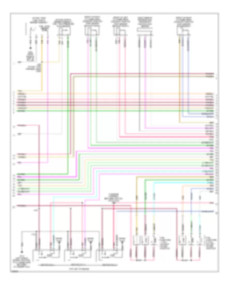
3.6L VIN 7, Engine Performance Wiring Diagram (2 of 5) for Saturn Outlook XE 2008
List of elements for 3.6L VIN 7, Engine Performance Wiring Diagram (2 of 5) for Saturn Outlook XE 2008:
- (top rear of fuel tank) evaporative emission (evap) canister vent solenoid valve
- (top right of engine)
- (under left side of dash) body control module (bcm)
- Acc
- Cnstr/ vent fuse 10a
- Driver information center (dic) display
- Dsply fuse 10a
- Fuel pump fuse 15a
- Fuel pump relay
- G110 (right front of engine, mounted to cylinder head)
- G112 (right rear of engine, mounted to cylinder head)
- Gmlan
- Hot at all times
- I/p fuse block (behind right end of dash)
- Ign
- Ign i/ii
- Ignition coil 1
- Ignition coil 3
- Ignition coil 5
- Ignition switch
- Instrument panel cluster (ipc)
- J131
- J139 (in engine harness, between ignition coils 3 & 5)
- J202
- J271
- Lines system computer data
- Logic
- Low engine oil pressure ind
- Mil ind
- Nca
- Off
- Run
- Spark plug
- Sply volt stop lp
- Start
- Tan
- Underhood fuse block (above right front wheelwell)
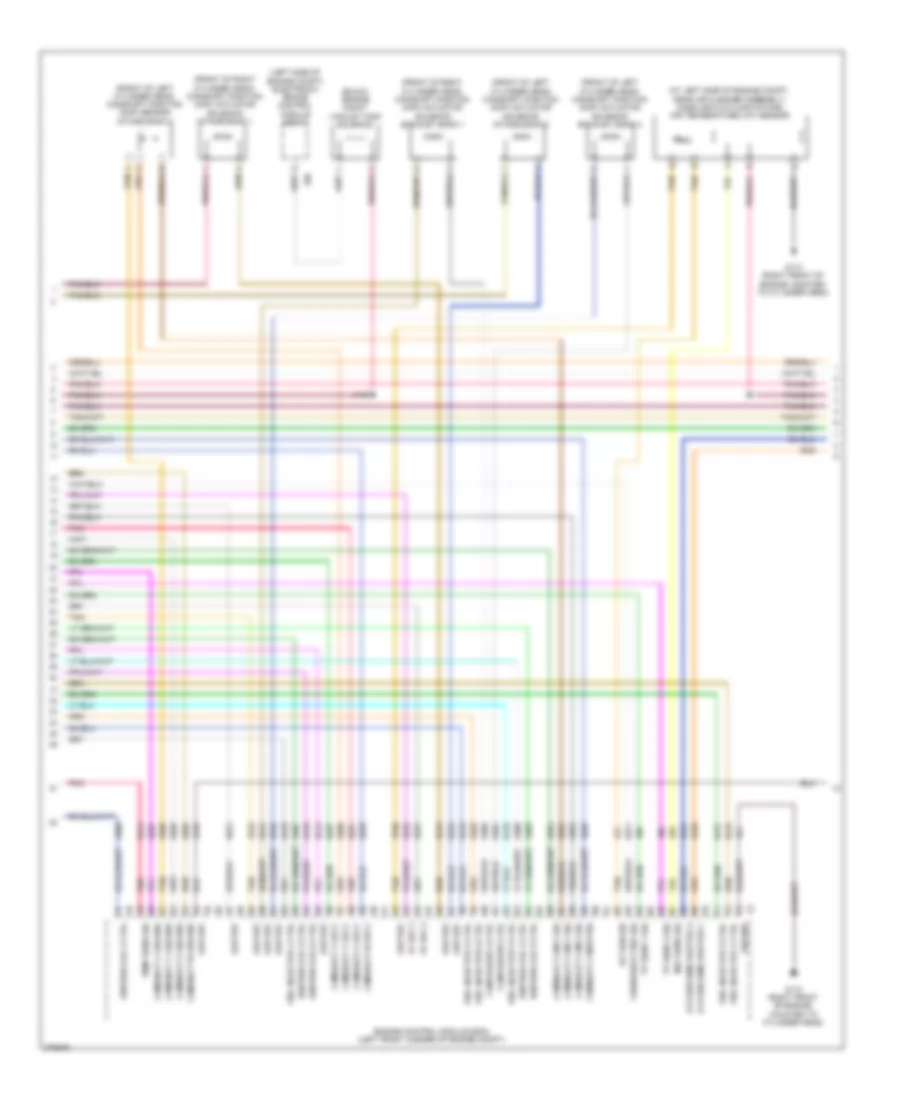
3.6L VIN 7, Engine Performance Wiring Diagram (3 of 5) for Saturn Outlook XE 2008
List of elements for 3.6L VIN 7, Engine Performance Wiring Diagram (3 of 5) for Saturn Outlook XE 2008:
- (front of left cylinder head) camshaft position (cmp) sensor exhaust bank 2
- (front of right cylinder head) camshaft position (cmp) sensor exhaust bank 1
- (front of right cylinder head) camshaft position (cmp) sensor intake bank 1
- (in engine harness, between ignition coils 4 & 6) j146
- (in fuel tank) fuel pump & sender assembly
- (on fuel pump & sender assembly) fuel tank pressure (ftp) sensor
- (right rear of engine block) crankshaft position (ckp) sensor
- (top left of engine)
- Fuel injectors 1, 3 & 5 (on right intake manifold)
- Fuel injectors 2, 4 & 6 (on left intake manifold)
- Fuel level sensor
- G114 (left side of engine, mounted to cylinder head between cylinders 4 & 6)
- G303 (near base of left "b" pillar)
- Ignition coil 2
- Ignition coil 4
- Ignition coil 6
- J133
- J135
- J137
- J144
- J395 (in fuel tank harness, near x305)
- Nca
- Pnk
- Pnk b
- Spark plug
- Tan
- Tan b
3.6L VIN 7, Engine Performance Wiring Diagram (4 of 5) for Saturn Outlook XE 2008
List of elements for 3.6L VIN 7, Engine Performance Wiring Diagram (4 of 5) for Saturn Outlook XE 2008:
- (at left side of engine compt, near air cleaner assembly) mass air flow (maf)/intake air temperature (iat) sensor
- (buick) engine mount vacuum tank solenoid
- (front of left cylinder head) camshaft position (cmp) actuator solenoid exhaust bank 2
- (front of left cylinder head) camshaft position (cmp) actuator solenoid intake bank 2
- (front of left cylinder head) camshaft position (cmp) sensor intake bank 2
- (front of right cylinder head) camshaft position (cmp) actuator solenoid exhaust bank 1
- (front of right cylinder head) camshaft position (cmp) actuator solenoid intake bank 1
- (left side of engine compt) electronic brake control module (ebcm)
- 5v ref 2
- Cam phaser 3 ctrl
- Cam phaser ctrl
- Camshaft cam w sig
- Camshaft cam x sig
- Camshaft cam y sig
- Camshaft cam z sig
- Camshaft w ground
- Camshaft w sply
- Camshaft x ground
- Camshaft x sply
- Camshaft y ground
- Camshaft y sply
- Camshaft z ground
- Camshaft z sply
- Crankshaft 60x sig
- Engine control module (ecm) (left front corner of engine compt)
- Fuel injector 1 ctrl
- Fuel injector 2 ctrl
- Fuel injector 3 ctrl
- Fuel injector 4 ctrl
- Fuel injector 5 ctrl
- Fuel injector 6 ctrl
- G110 (right front of engine, mounted to cylinder head)
- Ground
- Iat sen sig
- Ignition coil 2 ctrl
- Ignition coil 3 ctrl
- Ignition coil 4 ctrl
- Ignition coil 5 ctrl
- Ignition coil 6 ctrl
- J142
- Low ref
- Maf sens sig
- Oxygen sens heated a
- Oxygen sens heated c
- Pnk
- Tan
- Temp sens sig
- Tp sens 1 sig
- Tp sens 2 sig
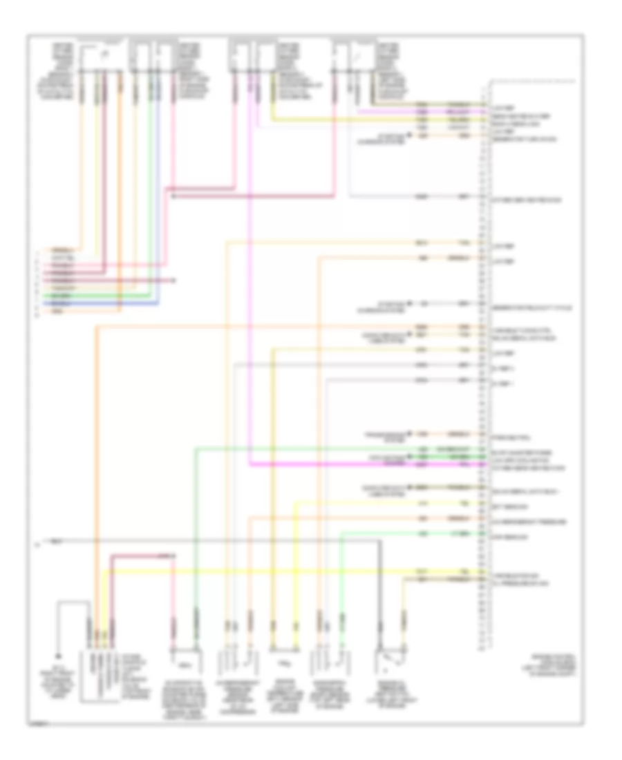
3.6L VIN 7, Engine Performance Wiring Diagram (5 of 5) for Saturn Outlook XE 2008
List of elements for 3.6L VIN 7, Engine Performance Wiring Diagram (5 of 5) for Saturn Outlook XE 2008:
- 5v ref 1
- 5v ref 2
- A/c refrigerant pressure
- A/c refrigerant pressure sensor (near rear of a/c compressor)
- Bank 2 sens 2 sig
- Barometric pressure (baro) sensor (top left rear of engine)
- Computer data lines system
- Cooling fans system
- Ect sens sig
- Engine control module (ecm) (left front corner of engine compt)
- Engine coolant temperature (ect) sensor (left side of engine)
- Engine oil pressure (eop) switch (lower left front of engine)
- Evap canister purge
- Evaporative emission (evap) canister purge solenoid valve (center rear of engine, near throttle body)
- Fused sply
- G110 (right front of engine, mounted to cylinder head)
- Generator field duty cycle
- Generator turn on sig
- Gmlan serial data bus +
- Gmlan serial data bus-
- Ground
- Heated oxygen sensor (ho2s) bank 1 sensor 1 (right side of engine, in exhaust manifold)
- Heated oxygen sensor (ho2s) bank 1 sensor 2 (in exhaust, downstream of catalytic converter)
- Heated oxygen sensor (ho2s) bank 2 sensor 1 (left side of engine, in exhaust manifold)
- Heated oxygen sensor (ho2s) bank 2 sensor 2 (in exhaust, downstream of catalytic converter)
- Intake manifold tuning (imt) solenoid valve (top front of engine)
- J140
- Low ref
- Low spd cooling fan
- Map sens sig
- Oil pressure sw sig
- Oxygen sen heated b sig
- Oxygen sens heated d sig
- Park/neutral
- Sens heated b hi ref
- Starting/ charging system
- Tan
- Transmissions system
- Variable pos
- Variable pos sig
- Variable tuning
- Variable tuning ctrl