ENGINE PERFORMANCE
2.2L VIN D
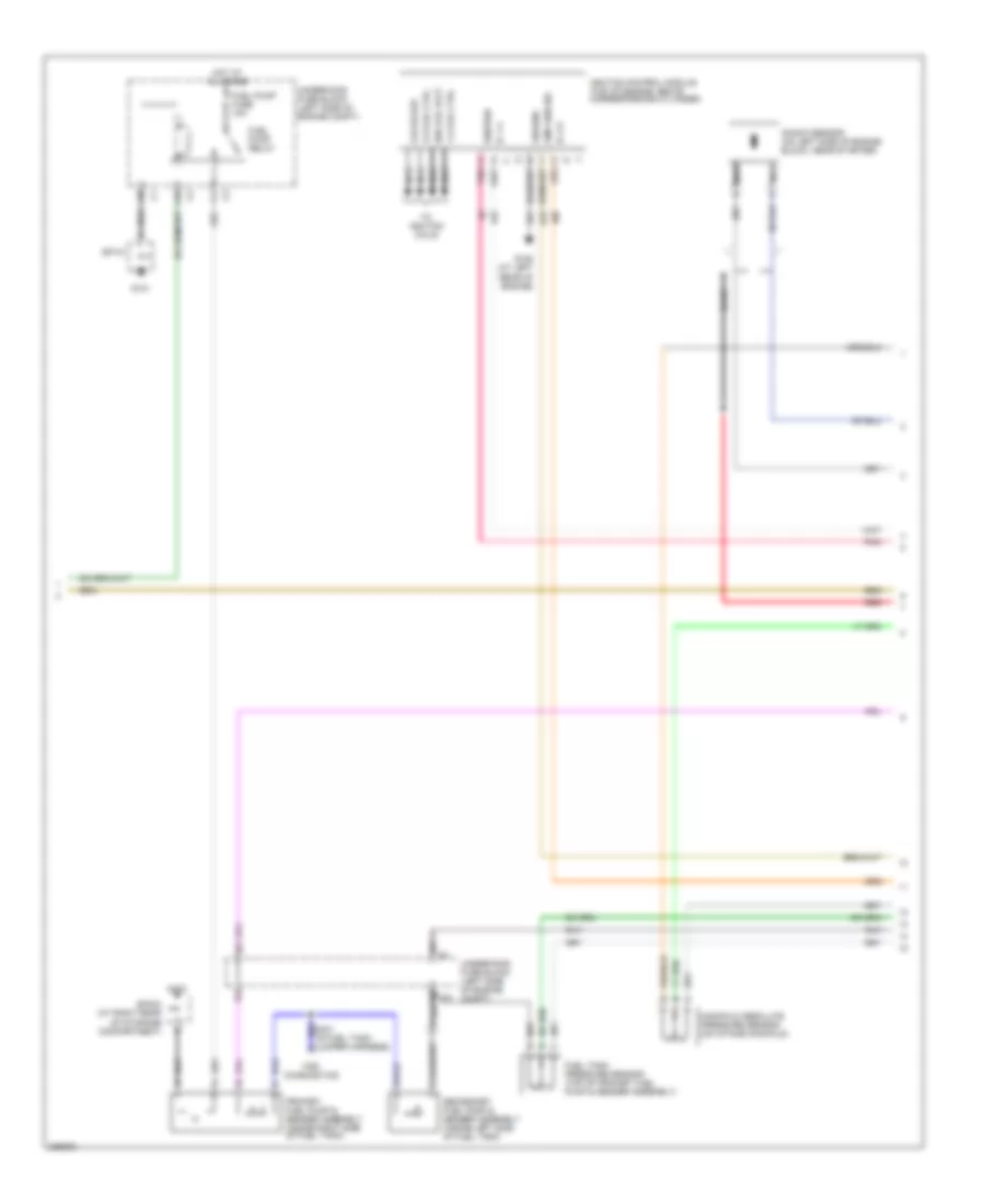
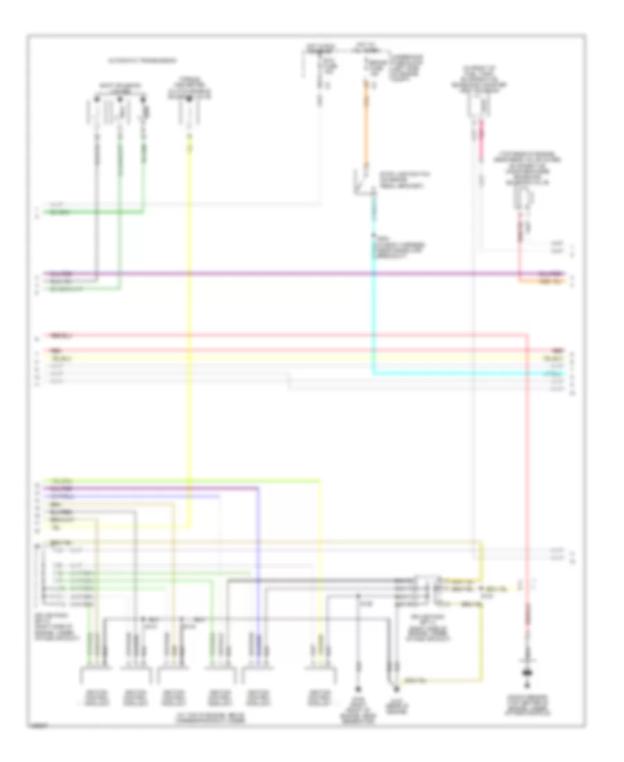
2.2L VIN D, Engine Performance Wiring Diagram (1 of 3) for Saturn Vue Red Line 2006

List of elements for 2.2L VIN D, Engine Performance Wiring Diagram (1 of 3) for Saturn Vue Red Line 2006:
- (at left rear of engine) g105
- (in a/c high side press line) a/c refrigerant pressure sensor
- (m/t)
- A/c press +5v
- A/c press lo
- A/c press sig
- A/c relay
- A/t
- A12
- Accelerator pedal position sensor (accelerator pedal linkage arm)
- Air conditioning system cooling fans system
- App 1 lo
- App 1 sig
- App 2 lo
- App 2 sig
- App1 5v ref a
- App2 5v ref a
- B12
- Back-up fuse 10a
- Battery
- Body control module (below front of center floor console)
- Brake fuse 15a
- Can high
- Can low
- Class 2 serial data
- Computer data lines system
- Cool fan rly
- Cooling fans system
- Cruise control system
- Cruise fuse 2a
- Cruise/ brake switch (on brake pedal bracket)
- Cruz on/off
- Cruz res/acl
- Cruz set/cst
- Crz brake sw
- Data link connector (lower left side of dash)
- Ecm/tcm fuse 10a
- Electronic brake control module (near left front shock tower)
- Engine control module (right side of engine compartment)
- Engine oil pressure switch (on engine block, near oil filter)
- Exterior lights system
- Fan rly 2 ctrl
- Fuel relay
- G107 (at rear of engine)
- Hot at all times
- Hot in run or start
- Ign 1 fuse 10 a
- Ignition
- Instrument panel cluster (ipc)
- Instrument panel fuse block (behind center of dash)
- Keyw seri data
- Logic
- M/t w/ abs
- M/t w/o abs
- Main relay
- Malfunction indicator lamp (mil)
- Mil control
- Oil press sig
- Output speed sensor
- Pnk
- Powertrain fuse 10a
- S304 (in body harness, near cross car breakout)
- Stop lamp sw
- Stop lamp switch (on brake pedal bracket)
- Tan
- Transmission control module (left side of engine compt)
- Underhood fuse block (left side of engine compt)
- Vehicle speed sensor (at rear of transmission)
- Vss sig
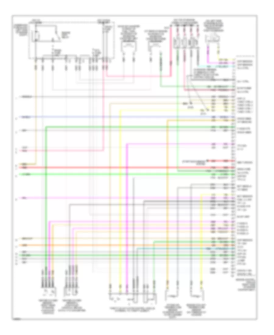
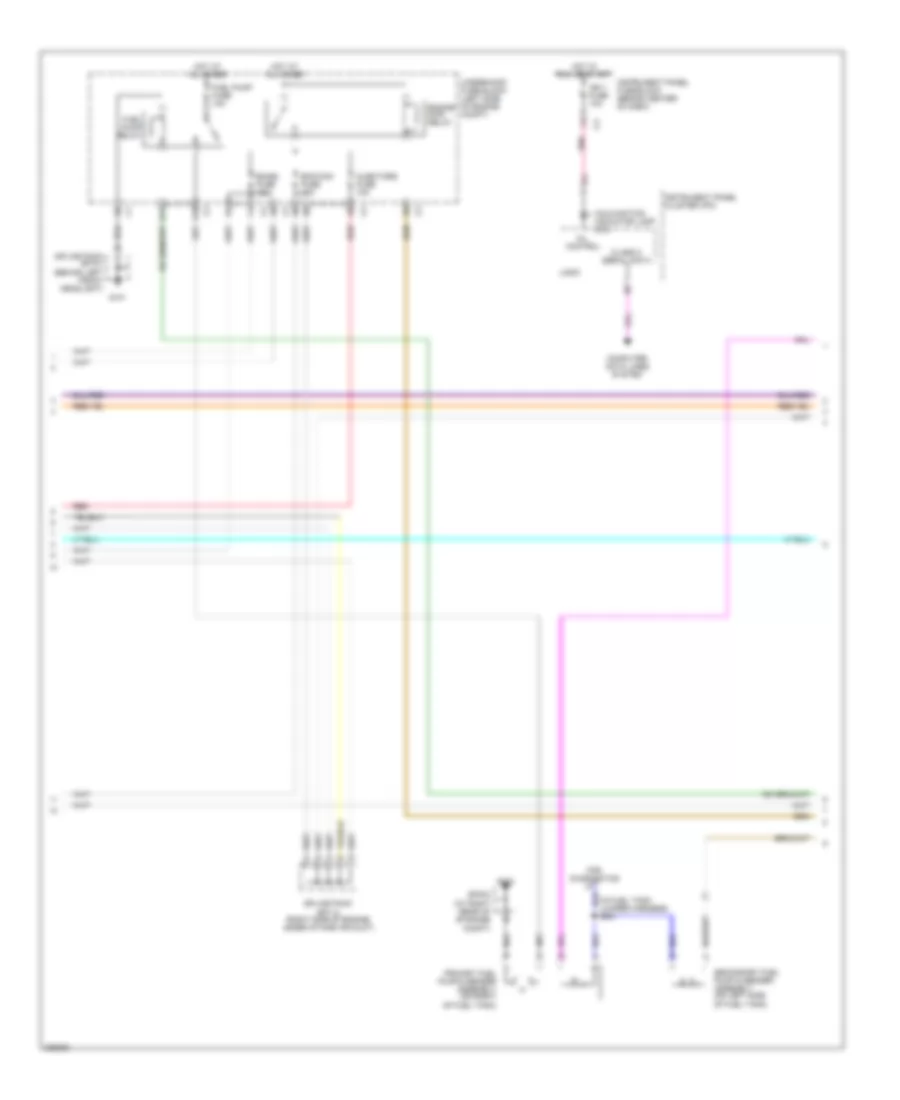
2.2L VIN D, Engine Performance Wiring Diagram (2 of 3) for Saturn Vue Red Line 2006
List of elements for 2.2L VIN D, Engine Performance Wiring Diagram (2 of 3) for Saturn Vue Red Line 2006:
- 1-4 coil ctrl
- 2-3 coil ctrl
- A pnk
- A10
- Bare
- C2 c2
- Cmp sen sig
- Csi pickup
- F11
- For diagnostics
- Fuel pump fuse 10a
- Fuel pump relay
- Fuel tank pressure sensor (top of primary fuel pump & sender assembly)
- G101
- G105 (at left rear of engine)
- G403
- Ground
- Hot at all times
- Ic 1-4
- Ic 2-3
- Ign coil volt
- Ignition
- Ignition control module (top of engine, above corresponding cylinder)
- Jumper harness)
- Knock sensor (on left side of engine block, near starter)
- Manifold absolute pressure sensor (on intake manifold)
- Nca
- Pnk
- Primary fuel pump & sender assembly (inside right side of fuel tank)
- Red
- Secondary fuel pump & sender assembly (inside left side of fuel tank)
- Sp101
- Sp403 (at right rear of storage compartment)
- To ignition coils
- Underhood fuse block (left side of engine compt)
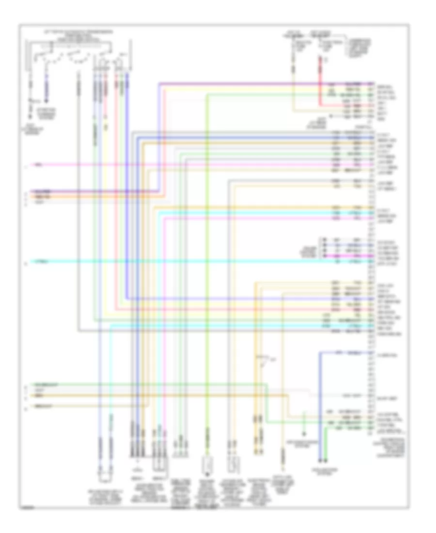
2.2L VIN D, Engine Performance Wiring Diagram (3 of 3) for Saturn Vue Red Line 2006
List of elements for 2.2L VIN D, Engine Performance Wiring Diagram (3 of 3) for Saturn Vue Red Line 2006:
- (at rear of engine) evaporative emissions canister purge solenoid
- (in engine harness, at breakout for throttle actuator control module)
- (on evap canister, in front of fuel tank) evaporative emissions canister vent solenoid
- (on left side of engine block, above starter) crankshaft position sensor
- (on top of engine, under intake runner) fuel injectors
- B11
- Ckp sens sig
- Cmp sens sig
- Drain wire
- Ect sens lo
- Ect sens sig
- Emiss fuse 10a
- Engine control module (right side of engine compartment)
- Engine coolant temperature sensor (on thermostat housing)
- Engine main relay
- Etc fuse 15a
- Evap purge
- Evap vent
- F ho2s hi
- F ho2s htr
- F ho2s lo
- Ftp +5v
- Ftp sig
- Fuel lvl sig
- Gen turn sig
- Heated oxygen sensor 1 (right rear of engine, in exhaust manifold)
- Heated oxygen sensor 2 (in exhaust manifold, behind catalytic converter)
- Hot at all times
- Hot in run or start
- Iat sens
- Iat sens sig
- Ic 1-4
- Ic 2-3
- Ign/inj fuse 15a
- Inj 1 ctrl
- Inj 2 ctrl
- Inj 3 ctrl
- Inj 4 ctrl
- Intake air temperature sensor (in engine compt, in air cleaner duct)
- Knock sens
- Lo ref
- Main rly ign
- Map +5v
- Map lo
- Map sig
- Nca
- Pnk
- R ho2s hi
- R ho2s htr
- R ho2s lo
- Red
- S101
- S109
- S110
- Starting/charging system
- Tan
- Throt ctrl 1
- Throt ctrl 2
- Throttle actuator control module (integral to throttle body)
- Tp 1 +5v
- Tp 1 lo
- Tp 1 sig
- Tp 2 +5v
- Tp 2 lo
- Tp 2 sig
- Underhood fuse block (left side of engine compt)
3.5L VIN 4
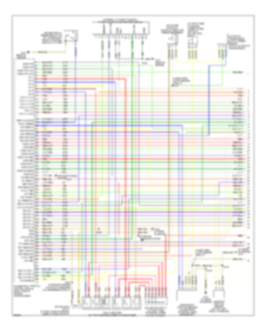
3.5L VIN 4, Engine Performance Wiring Diagram (1 of 5) for Saturn Vue Red Line 2006
List of elements for 3.5L VIN 4, Engine Performance Wiring Diagram (1 of 5) for Saturn Vue Red Line 2006:
- (at rear of engine) g107
- (at right side of engine, under intake air duct) splice pack sp114
- (in eng harn, in ckp sensor circuit)
- (in eng harn, in map sensor circuit) s115
- (in engine harness in pcm data sensors low reference circuit)
- (integral to throttle body) throttle actuator control module
- (on intake manifold) manifold absolute pressure sensor
- (partial)
- 3rd cltch sw
- 4th cltch sw
- 5 volt ref
- A/c ref sig
- Air conditioning system
- Automatic transmission output speed sensor (top of automatic transmission)
- Camshaft position sensor (on top left front of engine)
- Ckp sens a
- Ckp sens b
- Cmp pos sig
- Crankshaft position sensor (lower front of engine, near crankshaft)
- Ect sens sig
- Egr valve sig
- Etc cntrl
- Etc ctrl
- Etc sig
- Fuel injectors (on top of engine under intake runner)
- G107 (at rear of engine)
- G107 (rear of engine)
- Gen field
- Gen turn on
- Gnd
- Ho2s htr
- Ho2s htr low
- Ho2s input
- Ho2s low
- Ho2s low ref
- Ho2s pump
- Ho2s ref
- Ho2s sig
- Ho2s sig sens
- Iat sens 2
- Ign 1
- Ign coil 1
- Ign coil 2
- Ign coil 3
- Ign coil 4
- Ign coil 5
- Ign coil 6
- Inj 1
- Inj 2
- Inj 3
- Inj 4
- Inj 5
- Inj 6
- Iss high sig
- Knk sens sig
- Low ref
- Map sens sig
- Minhibit
- Mot inhibit
- Oil press sw
- Oss high sig
- Powertrain control module (right side of engine compartment)
- Ra oil press
- Red
- Rocker arm oil pressure switch (at lower right front of engine, above oil filter)
- S129
- S132
- S133
- S134
- S135
- Splice pack sp113 (at right side of engine, under intake air duct)
- Splice pack sp114 (at right side of engine, under intake air duct)
- Ssv hi ctrl 1
- Ssv hi ctrl 2
- Ssv hi ctrl 3
- Starting/ charging system
- Tcc enable
- Tcc vlv
- Tcc vlv low
- Tft sens sig
- Tls vlv hi a
- Tls vlv hi b
- Tls vlv lo a
- Tls vlv lo b
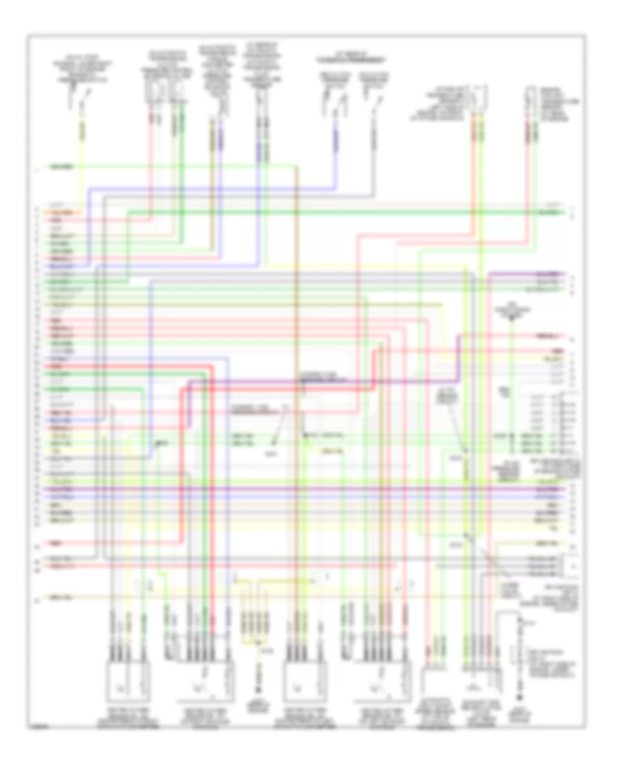
3.5L VIN 4, Engine Performance Wiring Diagram (2 of 5) for Saturn Vue Red Line 2006
List of elements for 3.5L VIN 4, Engine Performance Wiring Diagram (2 of 5) for Saturn Vue Red Line 2006:
- (at rear of automatic transmission)
- (at rear of automatic transmission) automatic transmission fluid temperature sensor
- (in a/c pressure sensor circuit)
- (in automatic transmission)
- (in automatic transmission) clutch pressure control solenoid valves
- (in bank 1 ho2 sensors circuit)
- (in bank 2 ho2 sensors circuit)
- (in egr valve circuit)
- (in tft sensor circuit)
- (on oil pump housing, lower right front of engine) engine oil pressure switch
- 3rd clutch pressure switch
- 4th clutch pressure switch
- Air conditioning system
- Automatic input shaft speed sensor (at top of automatic transmission)
- Engine coolant temperature sensor (at rear of engine)
- Exhaust gas recirculation valve (left rear of engine)
- G107 (rear of engine)
- Heated oxygen sensor (b1, s1) (on right exhaust manifold)
- Heated oxygen sensor (b1, s2) (downstream of right catalytic converter)
- Heated oxygen sensor (b2, s1) (on left exhaust manifold)
- Heated oxygen sensor (b2, s2) (downstream of left catalytic converter)
- Intake air temperature sensor 2 (left side of engine, on front of intake manifold)
- Nca
- Red
- S112
- S119
- S120
- S121
- S122
- S123
- S124
- S135
- Splice pack sp113 (at right side of engine, under intake air duct)
- Splice pack sp114 (at right side of engine intake air duct)
- Splice pack sp114 (at right side of engine, under intake air duct)
- Torque converter clutch pressure control solenoid valve
3.5L VIN 4, Engine Performance Wiring Diagram (3 of 5) for Saturn Vue Red Line 2006
List of elements for 3.5L VIN 4, Engine Performance Wiring Diagram (3 of 5) for Saturn Vue Red Line 2006:
- (at top of engine, above corresponding cylinder)
- (in front of fuel tank) evaporative emissions canister vent solenoid
- (top rear of engine, near rear valve cover) evaporative canister purge emissions solenoid valve
- Automatic transmission
- Brake fuse 15a
- Etc fuse 15a
- G107 (rear of engine)
- G109 (right front of engine, near generator)
- Hot at all times
- Hot in run or start
- Ignition control module 1
- Ignition control module 2
- Ignition control module 3
- Ignition control module 4
- Ignition control module 5
- Ignition control module 6
- Knock sensor (top center of engine, under intake manifold)
- Nca
- Pnk
- Red
- S125
- S130
- S131
- S134
- S304 (in body harness, near cross car breakout)
- Shift solenoid valves
- Splice pack sp113 (right side of engine, under intake air duct)
- Splice pack sp114 (right side of engine, under intake air duct)
- Stop lamp switch (on brake pedal bracket)
- Torque converter clutch enable solenoid valve
- Underhood fuse block (left side of engine compt)
3.5L VIN 4, Engine Performance Wiring Diagram (4 of 5) for Saturn Vue Red Line 2006
List of elements for 3.5L VIN 4, Engine Performance Wiring Diagram (4 of 5) for Saturn Vue Red Line 2006:
- Class 2 serial data
- Computer data lines system
- D10
- D11
- Ecm/cam fuse 15a
- Emiss fuse 10a
- Engine main relay
- For diagnostics
- Fuel pump fuse 10a
- Fuel pump relay
- G101
- G403
- Hot at all times
- Hot in run or start
- Ign 1 fuse 10a
- Injectors fuse 10a
- Instrument panel cluster (ipc)
- Instrument panel fuse block (behind center of dash)
- Logic
- Malfunction indicator lamp (mil)
- Mil control
- Pnk
- Primary fuel pump & sender assembly (on right of fuel tank)
- Red
- S401
- Secondary fuel pump & sender assembly (on left side of fuel tank)
- Sp403 (at right rear of storage compt)
- Splice pack sp101 (behind left front headlight)
- Splice pack sp113 (right side of engine, under intake air duct)
- Underhood fuse block (left side of engine compt)
3.5L VIN 4, Engine Performance Wiring Diagram (5 of 5) for Saturn Vue Red Line 2006
List of elements for 3.5L VIN 4, Engine Performance Wiring Diagram (5 of 5) for Saturn Vue Red Line 2006:
- (at rear of engine)
- (at top of automatic transmission) park/neutral position (pnp) switch
- (partial)
- 5 volt
- A/c cmp rel
- A/t
- Accelerator pedal position sensor (on accelerator pedal linkage arm)
- Air conditioning system
- Batt
- Can hi
- Can low
- Cc on sw
- Cc res/acc
- Cc set/cst
- Cooling fans system
- Cruise control system
- Data link connector (lower left side of dash)
- Drive sig
- Ecm/tcm fuse 10a
- Egr sol
- Electronic brake control module (near left front shock tower)
- Evap sol
- Evap vent
- F lvl sens
- F pmp rel
- F10
- Forward sig
- Ftp sens
- Fuel tank pressure sensor (on top of primary fuel pump & sender assembly)
- G107
- G107 (at rear of engine)
- Gnd
- Hi spd fan
- Hot at all times
- Hot in run or start
- Iat sens 1
- Ign 1
- Ing 1
- Int sig
- Intake air temperature sensor 1 (lower left side of air cleaner housing)
- Ist gear sig
- Low erf
- Low ref
- Low spd fan
- Main rel ctrl
- Nca
- Neutral sig
- Park sig
- Powertrain control module (right side of engine compartment)
- Pwr train fuse 10a
- Ra oil sol
- Red
- Rev sig
- Rocker arm oil control solenoid (lower right front of engine, near oil filter)
- S112
- Sens 1
- Sens 2
- Sens1 sig
- Sens2 sig
- Ser data
- Splice pack sp114 (at right side of engine, under intake air duct)
- Starting/ charging system
- Stp lp sw
- Tan
- Tcc brk sw
- Underhood fuse block (left side of engine compt)