POWER DISTRIBUTION
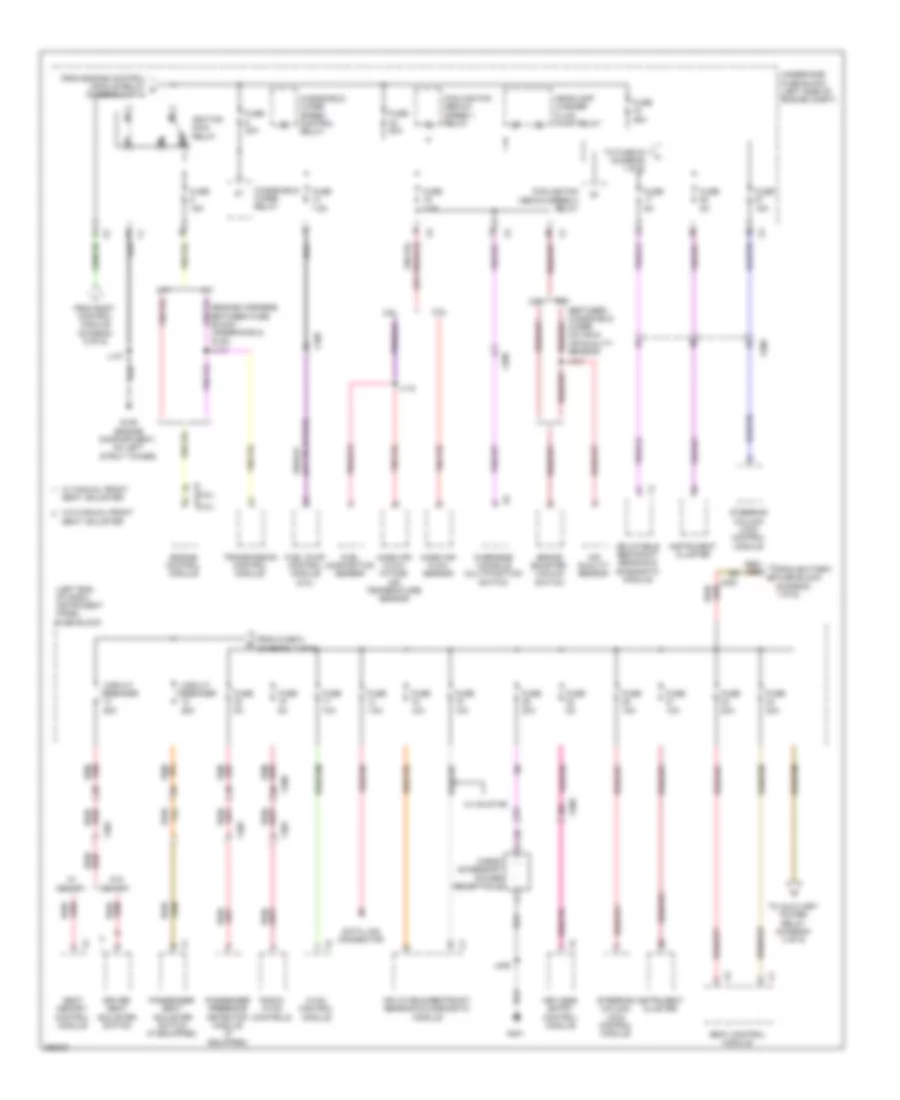
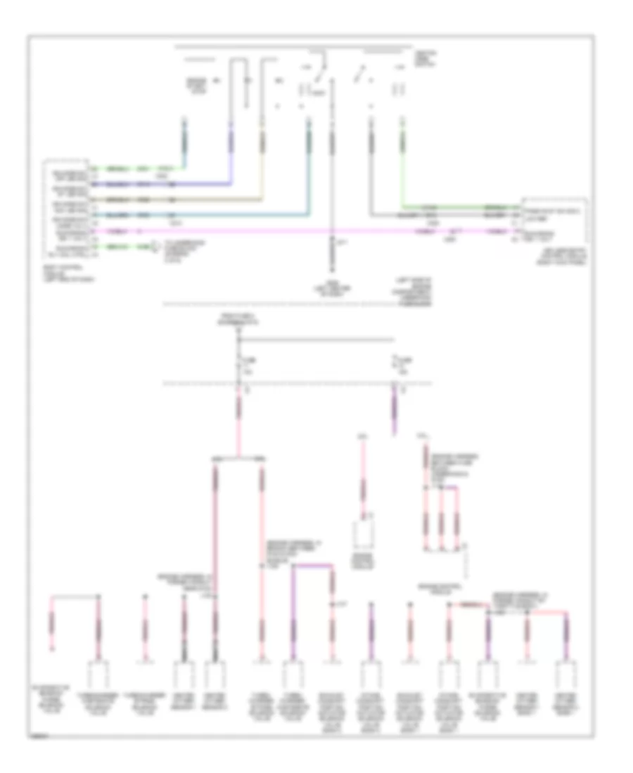
Power Distribution Wiring Diagram (1 of 6) for Saab 9-5 Aero 2011

List of elements for Power Distribution Wiring Diagram (1 of 6) for Saab 9-5 Aero 2011:
- (2.0l)
- (2.8l)
- (body harness, under cowling, between windshield wiper motor & air quality sensor) j132
- (diagram 2 of 6)
- (in main bundle between breakout to side impact sensor - left front & formed conduit near left front seat)
- (in main bundle between g201 & formed conduit near left front seat)
- (in main bundle between g401 & breakout to left rear wheel well) j416
- (in main bundle near breakout to recline motor) j365
- (left side of engine compt) underhood fuse block
- Battery
- Battery fuse block (left rear of engine compt)
- Driver cushion seat blower motor (w/ fan)
- Driver seat back blower motor (w/ fan)
- Driver seat lumbar support switch (if equipped)
- Driver window motor
- Electrical auxiliary heater
- Electronic brake control module
- Engine control module
- From fuse 52 j
- Fuel pump relay
- Fuse 100a
- Fuse 10a
- Fuse 15a
- Fuse 20a
- Fuse 250a
- Fuse 300a
- Fuse 30a
- Fuse 50a
- Fuse 5a
- Fuse 60a
- Generator
- Inside rear view mirror
- J309
- J316
- J355
- Left headlamp (w/ headlamp leveling)
- Nca
- Parking brake control module
- Passenger cushion seat blower motor (w/ fan)
- Passenger seat back blower motor (w/ fan)
- Passenger seat lumbar support switch (if equipped)
- Passenger window motor
- Power steering control module
- Rearview camera
- Recline motor)
- Red
- Right headlamp (w/ headlamp leveling)
- Secondary air injection pump relay (2.8l) fuse/ heater relay (2.0l)
- Starter motor
- Starter relay
- Tire pressure indicator module
- To auxiliary underhood fuse block (diagram 5 of 6)
- To fuse 32 (diagram 5 of 6)
- To instrument panel fuse block (diagram 2 of 6)
- To instrument panel fuse block (diagram 4 of 6)
- To rear body fuse block (diagram 5 of 6)
- Transmission control module
- Used) (not
- W/ light sensitive mirror
- W/ rearview camera
- W/ tire pressure indicator
- W/ tire pressure indicator, light sensitive mirror & rear view camera
- X110
- X120
- X200
- X301
- X307
- X407
- X500
- X600
Power Distribution Wiring Diagram (2 of 6) for Saab 9-5 Aero 2011
List of elements for Power Distribution Wiring Diagram (2 of 6) for Saab 9-5 Aero 2011:
- (2.0l) x1
- (2.8l) x2
- (between windshield wiper motor & air quality sensor)
- (engine harness, between fuse block - underhood & g120)
- (left end of dash) instrument panel fuse block
- 2.0l
- 2.8l
- 87a
- A/t
- Air quality sensor
- Body control module
- Brake booster vacuum switch
- Cargo accessory power receptacle
- Circuit breaker 25a
- Cooling fan medium speed 1 relay
- Cooling fan medium speed 2 relay
- Data link connector
- Driver seat adjuster switch
- Engine control module
- From battery fuse block (diagram 1 of 6)
- From body control module (diagram 6 of 6)
- From engine control module relay g (diagram 3 of 6)
- From fuse 9 (diagram 4 of 6)
- Fuel composition sensor
- Fuel pump control module (2.8l)
- Fuse 10a
- Fuse 15a
- Fuse 20a
- Fuse 25a
- Fuse 30a
- Fuse 5a
- Fuse 60a
- Fuse 7.5a
- G109 (engine compartment, on left strut tower)
- G401
- Headlamp washer fluid pump relay
- Hvac control module
- Ignition main relay
- Inflatable restraint sensing & diagnostic module
- Instrument cluster
- J114
- J118
- J131
- J137
- J409
- Keyless entry control module
- M/t
- Mass air flow sensor
- Mass air flow/ intake air temperature sensor
- Overhead console multifunction switch
- Passenger presence detection module (if equipped)
- Passenger seat adjuster switch (if equipped)
- Radio/ hvac controls
- Red/
- Seat adjuster
- Seat memory control module
- Steering column lock control module
- To auxiliary power relay (diagram 4 of 6)
- To fuse 54 (diagram 1 of 6)
- Transmission control module
- Underhood fuse block (left side of engine compt)
- W/ manual front seat adjuster
- W/ memory
- W/ on star
- W/o manual front
- W/o memory
- Windshield wiper relay
- Windshield wiper speed control relay
- X108
- X200
- X301
- X307
- X398
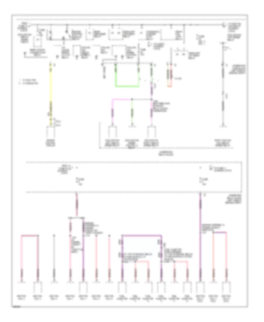
Power Distribution Wiring Diagram (3 of 6) for Saab 9-5 Aero 2011
List of elements for Power Distribution Wiring Diagram (3 of 6) for Saab 9-5 Aero 2011:
- (2.0l)
- (2.8l)
- (at top of engine, below intake manifold, in main bundle)
- (engine harness, in formed conduit by throttle body) j119
- (engine harness, in formed conduit near g123)
- (not used)
- 2.0l
- 2.8l
- A/c compr- essor clutch relay
- Cooling fan high speed relay
- Cooling fan left medium speed relay
- Cooling fan medium speed 1 relay
- Cooling fan medium speed 2 relay
- Cooling fan relay
- Cooling fan right medium speed relay
- Cooling fan speed control 2 relay
- Cooling fan speed control relay
- Engine control module
- Engine control module relay
- From fuse 46 l (diagram 3 of 6)
- From fuse 70 f (diagram 5 of 6)
- Front fog lamp relay
- Fuel injector
- Fuse 10a
- Fuse 15a
- Fuse 60a 30a
- Headlamp high beam relay
- Headlamp low beam relay
- Ignition coil 1
- Ignition coil 2
- Ignition coil 2 (2.8l)
- Ignition coil 3
- Ignition coil 4
- Ignition coil 4 (2.8l)
- Ignition coil 5
- Ignition coil 6 (2.8l)
- J106 (between main bundle & relay block - underhood)
- J120 (in formed conduit by throttle body)
- J121
- J144
- Rear defogger relay
- Rear window washer pump relay
- Right cooling fan medium speed relay
- To fuse 11 (diagram 6 of 6)
- To fuse 9 (diagram 3 of 6)
- To ignition main relay (diagram 2 of 6)
- Underhood fuse block (left side of engine compt)
- Underhood relay block
- Underhood relay block (left side of engine compt)
- W/ dual fan
- W/ hid
- W/ single fan
- Windshield washer pump relay
- X117
- X160 (fuel injector even harness, at top of engine, below intake manifold, in main bundle) j145
Power Distribution Wiring Diagram (4 of 6) for Saab 9-5 Aero 2011
List of elements for Power Distribution Wiring Diagram (4 of 6) for Saab 9-5 Aero 2011:
- (if equipped)
- (in branch between breakout to hvac control module & steering column)
- (in main bundle near data link resistor)
- (in main bundle rearward of formed conduit near left "b" pillar) j323
- (instrument panel harness, in main bundle in formed conduit, near center of instrument panel) j219
- (left end of dash)
- A/t
- Auxiliary power relay
- Block - instrument panel)
- Blower motor control module
- Body control module
- Center console accessory power receptacle
- Cigarette lighter receptacle
- Digital radio receiver control module
- Driver seatback video display (if equipped)
- Entertainment package
- From battery fuse block (diagram 1 of 6)
- From fuse 24 (diagram 2 of 6)
- Fuse 10a
- Fuse 15a
- Fuse 20a
- Fuse 25a
- Fuse 30a
- Fuse 50a
- G203
- G305
- Head-up display (w/ rearview camera)
- Info display module (if equipped)
- Instrument panel fuse block
- Instrument panel fuse block (left end of dash)
- Interior lights system
- J113
- J208
- J222
- J223 (in main bundle near fuse block - instrument panel)
- J224 (in main bundle near fuse block - instrument panel)
- J248
- M/t
- Mobile telephone control module (w/ wireless interface)
- Multimedia player interface module
- Parking assist control module
- Passenger seatback video display (if equipped)
- Radio
- Radio/ hvac controls (w/ info- tainment display)
- Rear audio control module (if equipped)
- Security siren (if equipped)
- To circuit breaker 12 (diagram 2 of 5)
- Transmission shift lever
- W/ rear seat
- W/o rear seat
- X200
- X200 (body harness, in main bundle rearward of formed conduit near left b-pillar, near c-pillar) j338
- X204
- X210
- X301
- X307
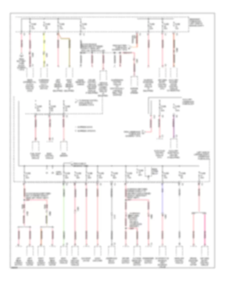
Power Distribution Wiring Diagram (5 of 6) for Saab 9-5 Aero 2011
List of elements for Power Distribution Wiring Diagram (5 of 6) for Saab 9-5 Aero 2011:
- (if equipped)
- (in branch between window switch - driver & lower door grommet) j508
- (in main bundle between g201 & formed conduit near left front seat) j307
- (in main bundle rearward of formed conduit near left b-pillar, near c-pillar) j340
- (left side of luggage compt) underhood fuse block
- 2.0l
- 2.8l
- Audio amplifier
- Auxiliary blower motor control module (w/ rear fan)
- Auxiliary electrical heater
- Auxiliary underhood fuse block
- Body control module
- Brake booster pump motor
- Cruise control vehicle distance sensor module (if equipped)
- Driver window switch
- Evaporative emission vent solenoid valve
- Express down
- Express up/down
- Formed conduit at center floor & formed conduit near right front seat) j344
- From battery fuse block (diagram 1 of 6)
- From battery fuse block e (diagram 1 of 6)
- From fuse 27 (diagram 1 of 6)
- From underhood fuse block (diagram 1 of 6)
- Fuel pump control module
- Fuse 100a
- Fuse 10a
- Fuse 20a
- Fuse 25a
- Fuse 30a
- Fuse 5a
- Fuse 60a
- Fuse 7.5a
- Fuse 80a
- Garage door opener
- Glow plug control module (2.0l)
- Headlamp control module
- Horn relay
- Inside rearview mirror
- Keyless entry control module
- Keyless entry control module (2.8l)
- Left rear window motor
- Left rear window switch
- Left side object sensor (if equipped)
- Outside rearview mirror switch
- Overhead console multi- function switch
- Passenger window switch
- Rain sensor
- Rear body fuse block (left side of engine compt)
- Rear differential clutch control module (awd)
- Rear wiper relay
- Right rear window motor
- Right rear window switch
- Right side object sensor (if equipped)
- Seat heating control module
- Sun roof motor
- Sunroof sunshade motor module (if equipped)
- Suspension control module (w/ continuously variable real time damping)
- To engine control module relay (diagram 3 of 6)
- Underhood relay block
- Vehicle direction camera control module (if equipped)
- X117
- X12
- X300
- X301
- X397
- X403
- X408
- X500
- X600
- X700
- X800
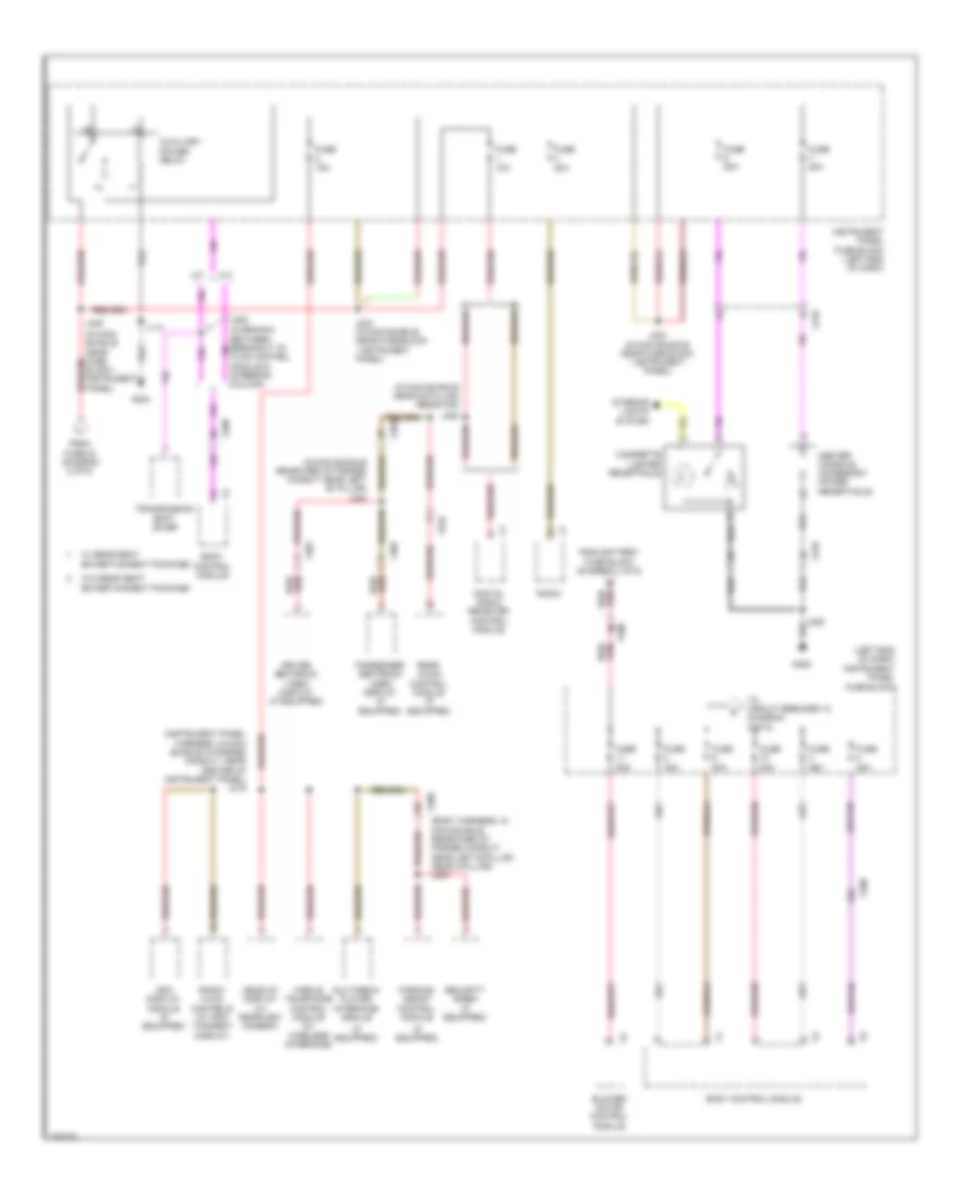
Power Distribution Wiring Diagram (6 of 6) for Saab 9-5 Aero 2011
List of elements for Power Distribution Wiring Diagram (6 of 6) for Saab 9-5 Aero 2011:
- (engine harness, between fuse block - underhood & g120) j117
- (engine harness, in branch between g120 & main bundle) j129
- (engine harness, in formed conduit by throttle body) j120
- (engine harness, in formed conduit near g123)
- (left side of engine compartment) underhood fuse block
- 2.0l
- 2.8l
- A10
- A12
- Accy
- B12
- Body control module (left end of dash)
- Engine control module
- Engine start/ stop
- Evaporative emission purge solenoid valve
- Exhaust camshaft position actuator solenoid valve bank 1
- Exhaust camshaft position actuator solenoid valve bank 2
- From fuse 8 (diagram 3 of 6)
- Fuse 10a
- Fuse 15a
- G206 (left center of dash)
- Heated oxygen sensor 1
- Heated oxygen sensor 1 bank 1
- Heated oxygen sensor 2
- Heated oxygen sensor 2 bank 1
- Ign mode sw acc led sig
- Ign mode sw mode volt
- Ign mode sw off led sig
- Ign mode sw st led sig
- Ignition mode switch
- Intake camshaft position actuator solenoid valve bank 1
- Intake camshaft position actuator solenoid valve bank 2
- J130
- J147
- J211
- Keyless entry control module (right kick panel)
- Low ref
- Nca
- Passive st sw sig 2
- Run/crank ign 1 volt
- Run/crank ign 1 volt x3
- Run/crank rly coil ctrl
- To underhood fuse block (diagram 2 of 6)
- Turbo- charger bypass solenoid valve
- Turbo- charger wastegate solenoid valve
- Turbocharger bypass solenoid valve
- Turbocharger wastegate solenoid valve
- X200
- X210
- X300