POWER DISTRIBUTION
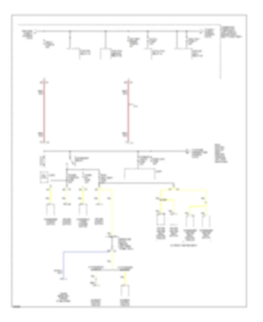
Power Distribution Wiring Diagram (1 of 5) for Saturn Aura XR 2007

List of elements for Power Distribution Wiring Diagram (1 of 5) for Saturn Aura XR 2007:
- (4 speed a/t)
- (6 speed a/t)
- (not used)
- (w/ front heated seats)
- 2.4l
- 3.5l/3.6l
- Abs fuse 24 60a
- Audio amp fuse 13 25a
- Audio amplifier
- B/u lp relay 33
- Batt
- Battery
- Bck/up lamps fuse 17 10a
- C3 d6
- Cig/aux fuse 20 20a
- Cigar lighter
- Console auxiliary power outlet
- Digital radio receiver (if equipped)
- Driver heated seat control module
- Drl fuse 46 15a
- Drl relay
- Ecm fuse 13 (2.4l/3.6l) 10a
- Electronic brake control module (ebcm)
- Engine control module (ecm)
- Eps fuse 41 80a
- From htd b seat fuse 14 (diagram 1 of 5)
- G303 (behind left front kick panel)
- Garage door opener (gdo) (if equipped)
- Generator
- Htd seat fuse 14 15a
- Passenger heated seat control module
- Power steering control module
- R/ wdo defog relay 26
- Rbec 1 fuse 22 60a
- Rear fuse block (behind left rear wheel well)
- Red
- Remote control door lock receiver (rcdlr)
- Rke/xm fuse 16 7.5a
- S/roof fuse 10 15a
- Starter generator control module (sgcm)
- Starter solenoid
- Sunroof control module (if equipped)
- Tcm fuse 42 10a
- To back-up lamps fuse 17 (diagram 1 of 5)
- To emission 2 fuse 5 (diagram 4 of 5)
- To ibcm 2 fuse 25 (diagram 2 of 5)
- Transmission control module (tcm)
- Underhood fuse block (left side of engine compt, next to battery)
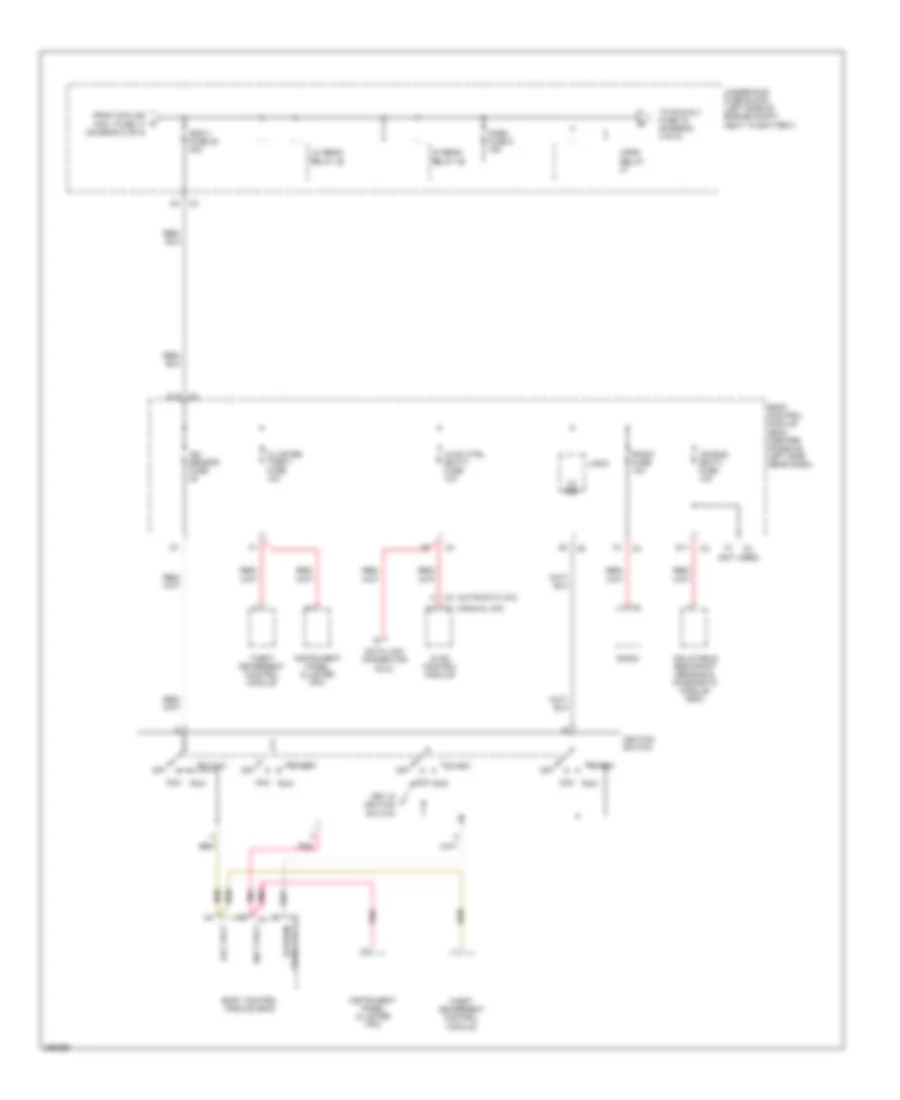
Power Distribution Wiring Diagram (2 of 5) for Saturn Aura XR 2007
List of elements for Power Distribution Wiring Diagram (2 of 5) for Saturn Aura XR 2007:
- (w/ front heated seat)
- 2.4l
- A/c clu fuse 1 10a
- A/c clutch relay 34
- Accessory relay
- Battery sense fuse 54 5a
- Body control module (bcm) (center console, left side near dash)
- Cool fan 1 fuse 17 30a
- Cool/fan ser/par relay 29
- Cooling fan 1 relay 28
- Door lock fuse 15a
- Driver heated seat control module
- Driver heated seat switch
- Driver window switch
- From eps a fuse 41 (diagram 1 of 5)
- Ibcm 2 fuse 25 50a
- Inside rearview mirror (if equipped)
- Interior lights fuse 10a
- Logic
- Passenger heated seat control module
- Passenger heated seat switch
- Passenger window switch
- Power windows fuse 30a
- Pwr/trn relay 33
- Rear fuse block (behind left rear wheel well)
- Rly ctrl
- Roof/ heat seat fuse 10a
- S301
- Sunroof control module
- To ibcm 1 fuse 20 (diagram 3 of 5)
- To power mirrors fuse (diagram 4 of 5)
- Underhood fuse block (left side of engine compt, next to battery)
- W/ panoramic sunroof
- W/ standard sunroof
- Windshield wiper/ washer switch
- Wiper sw fuse 10a
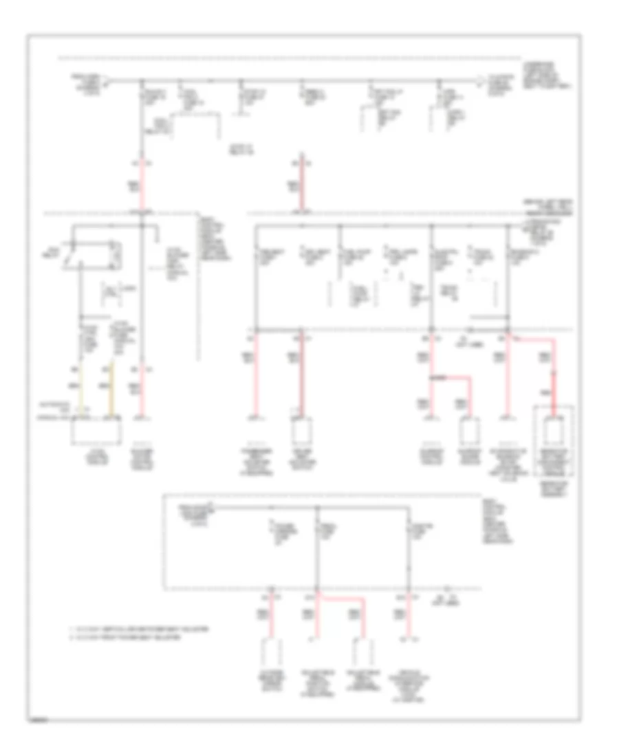
Power Distribution Wiring Diagram (3 of 5) for Saturn Aura XR 2007
List of elements for Power Distribution Wiring Diagram (3 of 5) for Saturn Aura XR 2007:
- (not used)
- 5v ref
- Acc run
- Acc volt
- Air bag (batt) fuse 10a
- Body control module (bcm)
- Body control module (bcm) (center console, left side near dash)
- C1 (manual a/c)
- C2 (automatic a/c)
- Cluster/ theft fuse 10a
- Crank volt off/run/
- D11
- D12
- Data link connector (dlc)
- From cooling fan 1 fuse 17 (diagram 2 of 5)
- Hi/ beam relay 35
- Horn fuse 8 15a
- Horn relay
- Hvac control module
- Hvac ctrl (batt) fuse 10a
- Ibcm 1 fuse 20 30a
- Ign 1 volt
- Ign sensor fuse 2a
- Ignition switch
- Inflatable restraint sensing & diagnostic module (sdm)
- Instrument panel cluster (ipc)
- Key in ignition switch
- Lo/ beam relay 38
- Logic
- Off
- Pnk
- Radio
- Radio fuse 10a
- Start
- Theft deterrent control module
- To run rly fuse 19 (diagram 4 of 5)
- Underhood fuse block (left side of engine compt, next to battery)
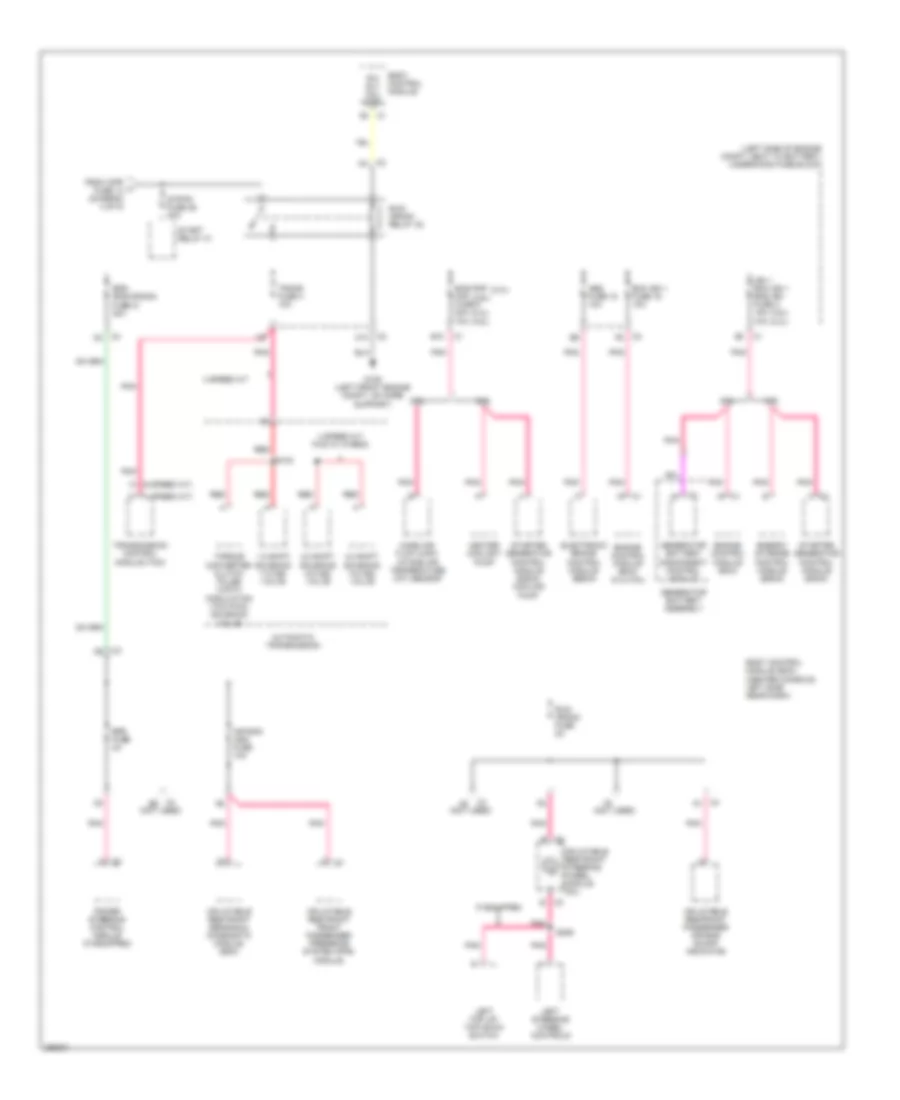
Power Distribution Wiring Diagram (4 of 5) for Saturn Aura XR 2007
List of elements for Power Distribution Wiring Diagram (4 of 5) for Saturn Aura XR 2007:
- (automatic a/c)
- (behind left rear wheel well) rear fuse block
- (manual a/c)
- (not used)
- Adjustable pedal module (if equipped)
- Adjustable pedal position switch (if equipped)
- Blower motor control module
- Body control module (bcm) (center console, left side near dash)
- Cool fan 2 fuse 18 30a
- Cool/ fan 2 relay 30
- D10
- Driver seat adjuster switch
- Drv seat fuse 2 30a
- E10
- Emission 2 fuse 5 10a
- Evaporative emission (evap) canister vent solenoid valve
- From door d lock fuse (diagram 2 of 5)
- From horn fuse 8 e (diagram 3 of 5)
- From r/wdo defog relay 26 (diagram 1 of 5)
- Frt fog lp fuse 10 15a
- Frt fog relay
- Fuel pump fuse 25 15a
- Fuel/ pump relay
- Genrator battery assembly
- Genrator battery disconnect control module
- Hvac blower fuse (manual a/c) 20a
- Hvac blower high relay (manual a/c)
- Hvac control module
- Hvac ctrl (ign) fuse 10a
- Logic
- Onstar fuse 10a
- Outside rearview mirror switch
- Passenger seat adjuster switch (if equipped)
- Pedal fuse 10a
- Power mirrors fuse 2a
- Prk lamps fuse 6 10a
- Prk lp relay
- Psg seat fuse 1 30a
- Rbec 2 fuse 23 60a
- Red
- Rly ctrl
- Run relay
- Run rly fuse 19 30a
- S405
- Sldg pnl roof fuse 9 25a
- Stop lp fuse 47 10a
- Stop lp relay 49
- Sunroof control module
- Sunroof shade module
- To strtr fuse 26 (diagram 5 of 5)
- Trunk fuse 22 10a
- Trunk relay
- Underhood fuse block (left side of engine compt, next to battery)
- Vehicle communication interface module (vcim) (w/ onstar)
- W/ 2 way vertical driver power seat adjuster
- W/ 8 way front power seat adjuster
- Wpr 1 relay
- Wpr fuse 14 25a
Power Distribution Wiring Diagram (5 of 5) for Saturn Aura XR 2007
List of elements for Power Distribution Wiring Diagram (5 of 5) for Saturn Aura XR 2007:
- (2.4l)
- (2.4l) (3.6l)
- (3.5l) (2.4l)
- (3.6l)
- (4 speed a/t)
- (6 speed a/t)
- (left side of engine compt, next to battery) underhood fuse block
- (not used)
- 1-2 shift solenoid (1-2 ss) valve
- 2-3 shift solenoid (2-3 ss) valve
- 2.4l
- 3.5l
- 3.6l
- 4 speed a/t
- 4 speed a/t fwd w/ hybrid
- 4-3 shift solenoid (4-3 ss) valve
- Abs fuse 15 10a
- Air bag (ign) fuse 10a
- Automatic transmission
- B10
- Bas pmp maf fuse 5 20a 10a
- Body control module
- Body control module (bcm) (center console, left side near dash)
- C10
- C2 f6
- Ecm ign 1 fuse 16 10a
- Electronic brake control module (ebcm)
- Energy storage control module (escm)
- Engine control module (ecm)
- Engine control module (ecm) (2.4l/3.6l)
- Eps fuse 2a
- From wpr fuse 14 (diagram 4 of 5)
- G109 (left front engine compt, on core support)
- Generator battery assembly
- Generator battery disconnect control module
- Heater coolant pump
- Ibcm (run/crank) fuse 21 30a
- If equipped
- Ign 1 ecm ign 1 bas ign fuse 3 15a 10a
- Inflatable restraint front passenger presence system (pps) module
- Inflatable restraint passenger air bag on/off indicator
- Inflatable restraint sensing & diagnostic module (sdm)
- Inflatable restraint steering wheel module coil
- Left steering wheel controls
- Left top up/ top down switch
- Mass air flow (maf)/ intake air temperature (iat) sensor
- Pnk
- Power steering control module (if equipped)
- R/c rly coil ctrl
- Red
- Run/ crank fuse 2a
- Run/ crank relay 32
- S103
- S209
- Start relay 31
- Starter generator control module (sgcm)
- Starter generator control module (sgcm) cooling pump
- Strtr fuse 26 30a
- Torque converter clutch pulse width modulation (tcc pwm) solenoid valve
- Trans fuse 4 10a
- Transmission control module (tcm)