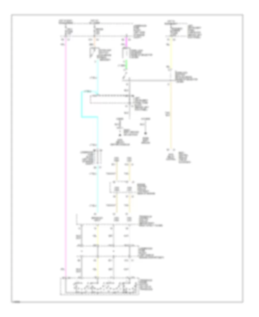
SHIFT INTERLOCKS
Shift Interlock Wiring Diagram for Saturn LW300 2001
List of elements for Shift Interlock Wiring Diagram for Saturn LW300 2001:
- A10
- A12
- B11
- B12
- Base body ground
- Body control module (top of glove box)
- Brake 15a 10a
- Brake sw input
- Btsi relay control
- Btsi/bcm/ mirror fuse 10a
- Can high
- Can low
- E11
- Engine control module (top right rear of engine)
- F10
- F11
- G302 (below center console)
- Hot at all times
- Hot in accy, run & crank
- Hot in run & accy
- Ign 0 fuse 10a
- Left instrument panel fuse block (behind left kick panel)
- Park lock solenoid (base of selector lever)
- Parklock switch/ btsi solenoid (base of selector lever)
- Right body ground splice pack
- Stoplamp switch (on brake pedal bracket)
- Tan
- Transaxle control module (behind right front strut tower)
- Transaxle range switch (on top of transaxle)
- Underhood fuse block (left side of engine compartment)
- Underhood fuse block (left side of engine compt)
- W/o rke
- W/rke
 English