STARTING/CHARGING
2.0L TURBO
2.0L Turbo, Charging Wiring Diagram for Saab 9-3 Aero 2007

List of elements for 2.0L Turbo, Charging Wiring Diagram for Saab 9-3 Aero 2007:
- B16
- Battery
- E126
- E127
- G2 (on side of left-hand structural member on connector console)
- G25 (on transmission)
- Generator
- Power distribution system
- Red
- Starter motor
- Trionic engine control module (front of engine)
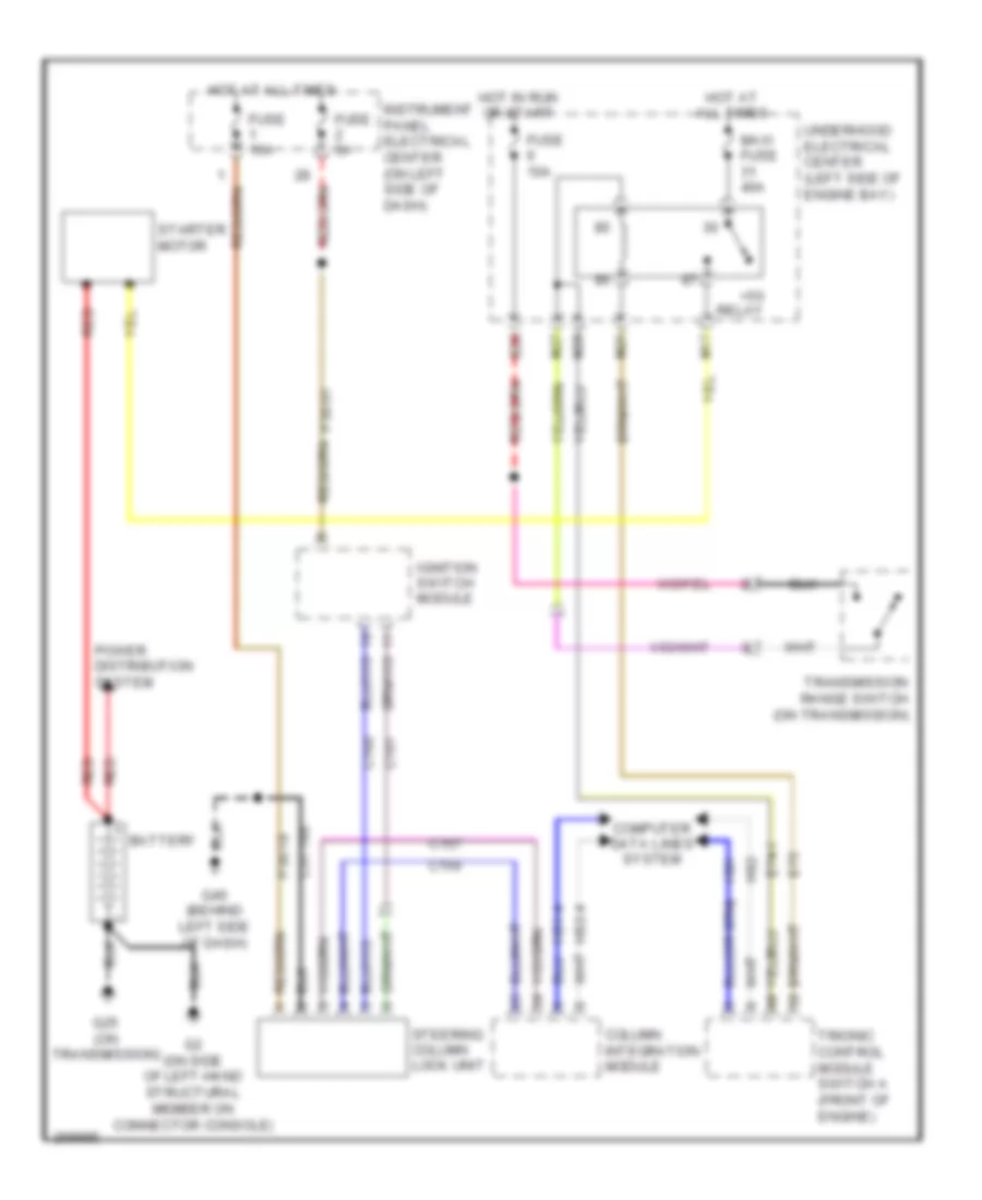
2.0L Turbo, Starting Wiring Diagram, A/T for Saab 9-3 Aero 2007
List of elements for 2.0L Turbo, Starting Wiring Diagram, A/T for Saab 9-3 Aero 2007:
- +50 relay
- B20
- Battery
- C156
- C157
- C160
- C161
- C31-160
- Column integration module
- Computer data lines system
- E74-1
- E75
- Fuse 10a
- Fuse 15a
- Fuse 5a
- G2 (on side of left-hand structural member on connector console)
- G25 (on transmission)
- G40 (behind left side of dash)
- Hot at all times
- Hot in run or start
- Hs1
- Hs1-4
- Hs2
- Hs2-4
- Ignition switch module
- Instrument panel electrical center (on left side of dash)
- M17
- M21
- M27
- M28
- Maxi fuse 40a
- P30-18
- P30-61
- Power distribution system
- Red
- Starter motor
- Steering column lock unit
- Transmission range switch (on transmission)
- Trionic control module switch a (front of engine)
- Underhood electrical center (left side of engine bay)
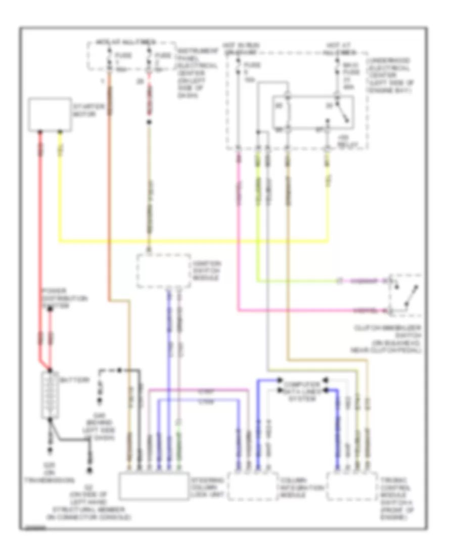
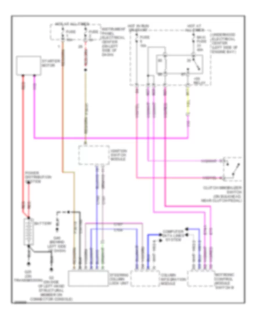
2.0L Turbo, Starting Wiring Diagram, M/T for Saab 9-3 Aero 2007
List of elements for 2.0L Turbo, Starting Wiring Diagram, M/T for Saab 9-3 Aero 2007:
- +50 relay
- Battery
- C156
- C157
- C160
- C161
- C31-160
- Clutch immobilizer switch (on bulkhead, near clutch pedal)
- Column integration module
- Computer data lines system
- E74-1
- E75
- Fuse 10a
- Fuse 15a
- Fuse 5a
- G2 (on side of left-hand structural member on connector console)
- G25 (on transmission)
- G40 (behind left side of dash)
- Hot at all times
- Hot in run or start
- Hs1
- Hs1-4
- Hs2
- Hs2-4
- Ignition switch module
- Instrument panel electrical center (on left side of dash)
- M17
- M21
- M27
- M28
- Maxi fuse 40a
- P30-18
- P30-61
- Power distribution system
- Red
- Starter motor
- Steering column lock unit
- Trionic control module switch a (front of engine)
- Underhood electrical center (left side of engine bay)
2.8L TURBO
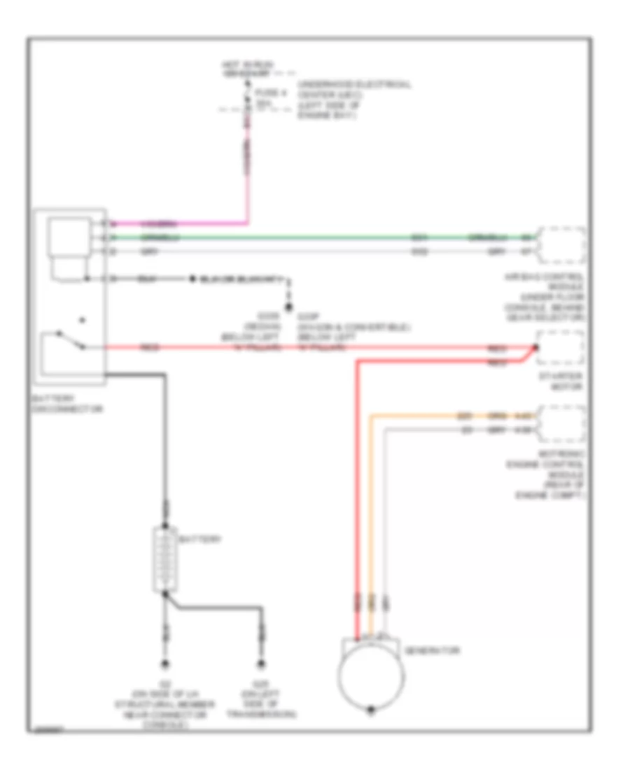
2.8L Turbo, Charging Wiring Diagram for Saab 9-3 Aero 2007
List of elements for 2.8L Turbo, Charging Wiring Diagram for Saab 9-3 Aero 2007:
- A36
- A43
- Air bag control module (under floor console, behind gear selector)
- Battery
- Battery disconnector
- Fuse 4 30a
- G2 (on side of lh structural member near connector console)
- G25 (on left side of transmission)
- G33p (wagon & convertible) (below left "a" pillar)
- G33s (sedan) (below left "a" pillar)
- Generator
- Hot in run or start
- Motronic engine control module (rear of engine compt)
- Nca
- Red
- S51
- S52
- Starter motor
- Underhood electrical center (uec) (left side of engine bay)
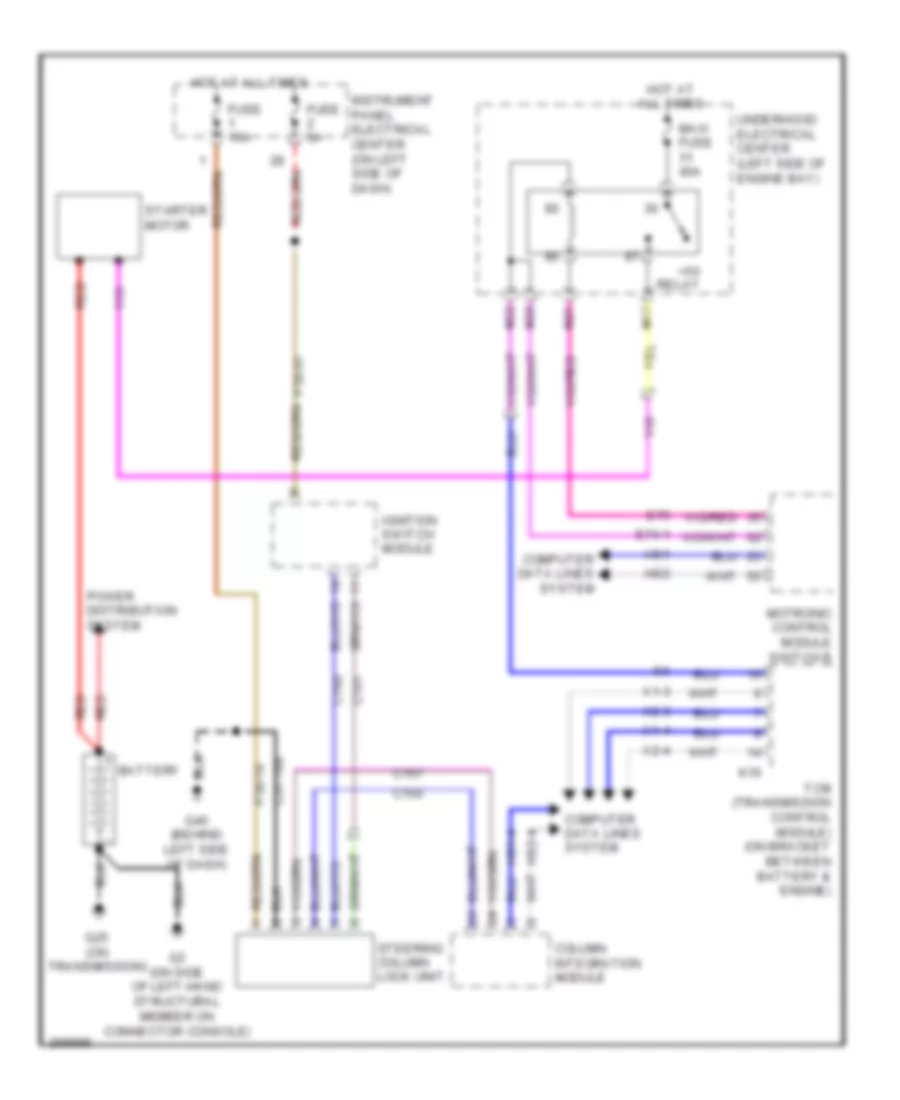
2.8L Turbo, Starting Wiring Diagram, A/T for Saab 9-3 Aero 2007
List of elements for 2.8L Turbo, Starting Wiring Diagram, A/T for Saab 9-3 Aero 2007:
- +50 relay
- Battery
- C156
- C157
- C160
- C161
- C31-160
- Column integration module
- Computer data lines system
- E74-1
- E75
- Fuse 15a
- Fuse 5a
- G2 (on side of left-hand structural member on connector console)
- G25 (on transmission)
- G40 (behind left side of dash)
- Hot at all times
- Hs1
- Hs1-4
- Hs2
- Hs2-4
- Ignition switch module
- Instrument panel electrical center (on left side of dash)
- K16
- M17
- M21
- M22
- M28
- Maxi fuse 40a
- Motronic control module switch b
- P30-18
- P30-61
- Power distribution system
- Red
- Starter motor
- Steering column lock unit
- Tcm (transmission control module) (on bracket between battery & engine)
- Underhood electrical center (left side of engine bay)
- X1-3
- X1-4
- X2-3
- X2-4
2.8L Turbo, Starting Wiring Diagram, M/T for Saab 9-3 Aero 2007
List of elements for 2.8L Turbo, Starting Wiring Diagram, M/T for Saab 9-3 Aero 2007:
- +50 relay
- Battery
- C156
- C157
- C160
- C161
- C31-160
- Clutch immobilizer switch (on bulkhead, near clutch pedal)
- Column integration module
- Computer data lines system
- E74-1
- E75
- Fuse 10a
- Fuse 15a
- Fuse 5a
- G2 (on side of left-hand structural member on connector console)
- G25 (on transmission)
- G40 (behind left side of dash)
- Hot at all times
- Hot in run or start
- Hs1-2
- Hs2-2
- Hs2-4
- Ignition switch module
- Instrument panel electrical center (on left side of dash)
- M17
- M21
- M27
- M28
- Maxi fuse 40a
- Motronic control module switch b
- P30-18
- P30-61
- Power distribution system
- Red
- Starter motor
- Steering column lock unit
- Underhood electrical center (left side of engine bay)