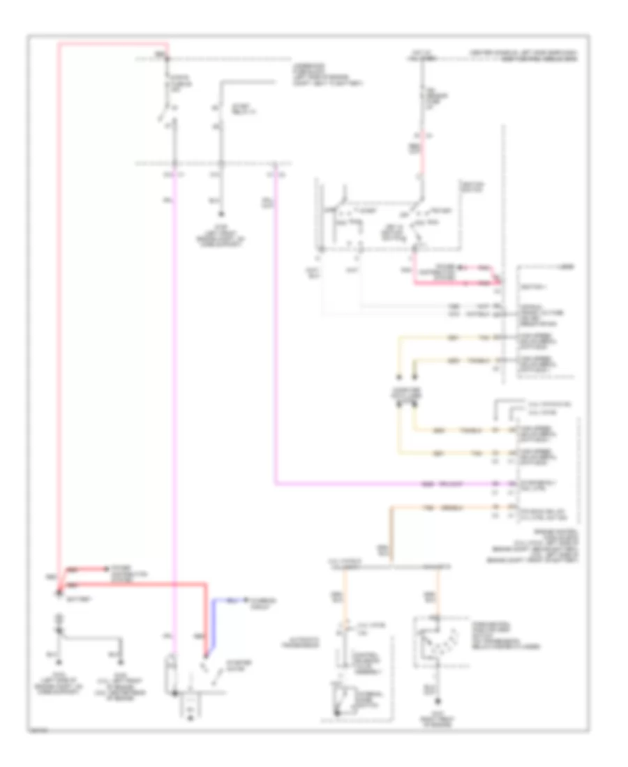
STARTING/CHARGING
Charging Wiring Diagram for Saturn Aura Green Line 2009

List of elements for Charging Wiring Diagram for Saturn Aura Green Line 2009:
- 2.4l (vin b)
- 3.6l
- Batt
- Battery
- Battery current sensor
- Battery position voltage
- Body control module (bcm) (center console, left side near dash)
- Charge ind
- Cluster/ theft fuse 10a
- Computer data lines system
- Data bus +
- Data bus -
- Engine control module (ecm) (3.6l: left side of engine compt, front of battery)
- F1 x4
- G104 (left side of engine compt, on core support)
- G105 (2.4l: left front of engine) (3.6l: center rear of engine)
- Gen field duty cycle sig
- Gen turn on sig
- Generator
- High speed gmlan serial data bus +
- High speed gmlan serial data bus -
- Hot at all times
- Ign
- Instrument panel cluster (ipc)
- Logic
- Low ref
- Pnk
- Power distribution system
- Red
- Sens sig
- Serial data
- Starter motor
- Tan
- Tan/
- Volt
Starting Wiring Diagram for Saturn Aura Green Line 2009
List of elements for Starting Wiring Diagram for Saturn Aura Green Line 2009:
- (center console, left side near dash)
- 2.4l (vin 5)
- 2.4l (vin 5) & 3.6l
- 2.4l (vin b)
- 2.4l (vin b) & 3.6l (vin 7)
- 3.6l
- Acc
- Automatic transmission
- Battery
- Body control module (bcm)
- C1 x2
- C10
- Charging circuit
- Computer data lines system
- Control solenoid valve assembly
- D1 x4
- D12 x1
- Engine control module (ecm) (2.4l (vin 5): left side of engine compt, behind battery) (3.5l: left side of engine compt, front of battery)
- G104 (left side of engine compt, on core support)
- G105 (2.4l: left front of engine) (3.6l: center rear of engine)
- G107 (right front of engine)
- G109 (left front engine compt, on core support)
- High speed gmlan serial data bus +
- High speed gmlan serial data bus -
- Hot at all times
- Ign sensor fuse 2a
- Ignition 1
- Ignition switch
- Internal mode switch
- Key in ignition switch
- Logic
- Off
- Off/run crank voltage ign key resistor sig
- P/n sig & ign lck cyl ctrl act sig
- Park/neutral position (pnp) switch (on transmission, below master cylinder)
- Pnk
- Power distribution system
- Red
- Run
- Start
- Start relay 31
- Starter motor
- Starter rly coil ctrl
- Strtr fuse 26 30a
- Tan
- Underhood fuse block (left side of engine compt, next to battery)