SUPPLEMENTAL RESTRAINTS
Supplemental Restraints Wiring Diagram for Saturn L300 2004
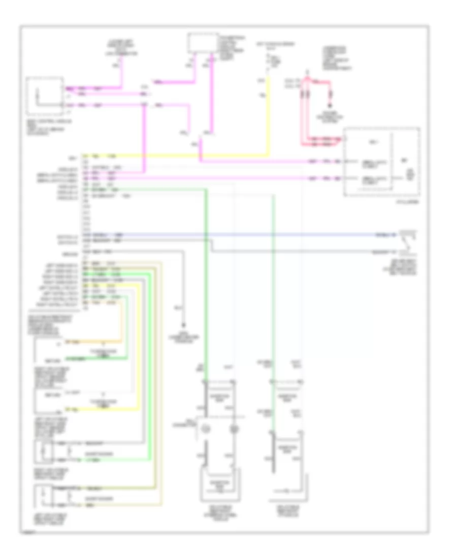
List of elements for Supplemental Restraints Wiring Diagram for Saturn L300 2004:
- (2.2l)
- (3.0l)
- (lower left side of dash) data link connector
- 2.2l
- 3.0l
- A10
- A11
- A12
- A13
- A14
- A15
- A16
- A17
- A18
- Air bag ind
- B tan
- B10
- Body control module (bcm) (left of i/p, behind glove box)
- D10
- Driver seat belt switch (in driver's seat belt buckle)
- G303 (under center console)
- Ground
- Hot in run & crank
- I/p cluster
- Ign 1
- Ign 1 fuse 10a
- Inflatable restraint i/p module
- Inflatable restraint sensing & diagnostic module (sdm) (under rear of floor console)
- Inflatable restraint steering wheel module
- Left inflatable restraint side impact module
- Left inflatable restraint side impact sensor (on lower left "b" pillar)
- Left satellite in
- Left satellite out
- Left side mod hi
- Left side mod lo
- Module hi
- Module lo
- Nca
- Pnk
- Power distribution system
- Powertrain control module (right rear of eng compt) c1
- Return
- Right inflatable restraint side impact module
- Right inflatable restraint side impact sensor (on lower right "b" pillar)
- Right satellite in
- Right satellite out
- Right side mod hi
- Right side mod lo
- Roll connector
- Serial data class 2
- Shorting bar
- Switch hi
- Switch lo
- Tan
- Twisted pair wires
- Underhood fuse block (uhfb) (left side of engine compartment)
 English