SUPPLEMENTAL RESTRAINTS
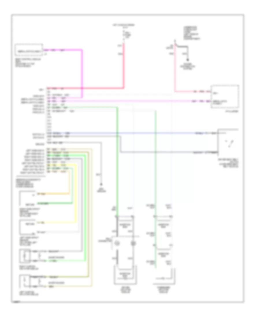
Supplemental Restraint Wiring Diagram for Saturn LW200 2001
List of elements for Supplemental Restraint Wiring Diagram for Saturn LW200 2001:
- A10
- A11
- A12
- A13
- A14
- A15
- A16
- A17
- A18
- B tan
- Body control module (bcm) (mounted to top of glove box)
- D10
- D5 (or f8)
- Driver inflator module
- Driver seat belt switch (in driver's seat belt buckle)
- Ground
- Hot in run & crank
- I/p cluster
- Ign 1
- Ign 1 fuse 10a
- Left curtain inflator module
- Left sattelite in
- Left sattelite out
- Left side impact sensor (on lower left "b" pillar)
- Left side mod hi
- Left side mod lo
- Module hi
- Module lo
- Nca
- Passenger inflator module
- Pnk
- Power distribution system
- Return
- Right curtain inflator module
- Right sattelite in
- Right sattelite out
- Right side impact sensor (on lower right "b" pillar)
- Right side mod hi
- Right side mod lo
- Roll connector
- Sdm ground
- Sensing & diagnostic module (sdm) (under rear of floor console)
- Serial data class 2
- Shorting bar
- Switch hi
- Switch lo
- Tan
- Underhood fuse block (uhfb) (left side of engine compartment)
 English