TRANSMISSION
A/T Wiring Diagram for Saab 9-3 Viggen 2000
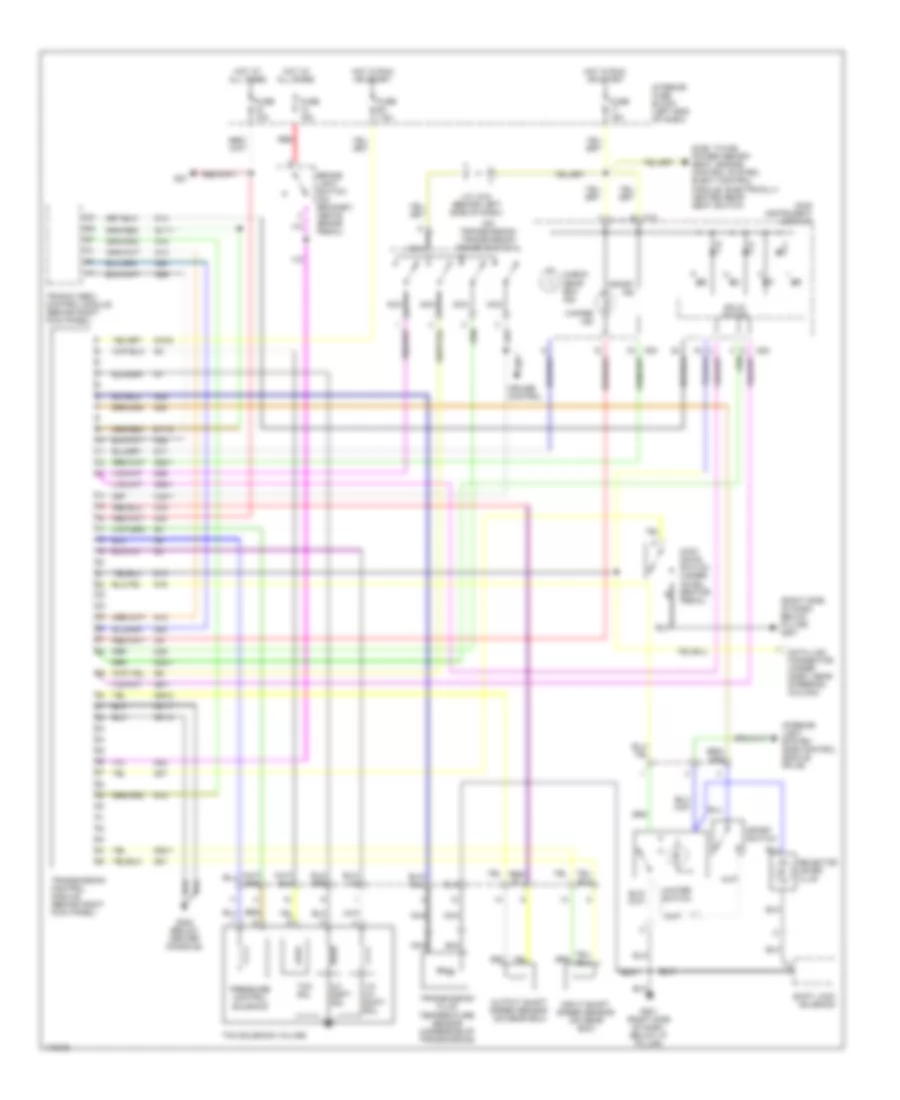
List of elements for A/T Wiring Diagram for Saab 9-3 Viggen 2000:
- (on transmission) transmission range switch 1
- (right side of dash, below pillar) g201
- 1/2- 3/4 shift sol
- 2/3 shift sol
- All times
- Brake light switch (on bracket, above brake pedal)
- C35-1
- Check gear box ind
- Cruise control
- D13
- D14
- Data link connector (under dash, near steering column)
- Dice, twice, power memory seat, engine control system, elect control module, electrically heated rear seat switch
- E17-1
- E17-5
- Fuse 10a
- Fuse 15a
- Fuse 6a 7.5a
- G12
- G13
- G15-2
- G16
- G17
- G19
- G20-1
- G20-2
- G201 (right side of dash, below "a" pillar)
- G21
- G23
- G25
- G26
- G27
- G28
- G28-1
- G30
- G302 (below center console)
- G31-1
- G31-2
- G34-1
- G35
- G36
- G36-1
- G80
- G9-1
- Hot at
- Hot in run or start
- I24
- Input shaft speed sensor (on gear box)
- Interior fuse block (left end of dash)
- Interior light system (dice control module, pin 49)
- J/c (jh4) (behind left side of dash)
- K12
- K20
- K22
- Kick- down switch (under accel- erator pedal)
- Main instrument display
- Nca
- Output shaft speed sensor (on gear box)
- Pressure control solenoid
- Red
- Selector lever illum
- Shift lock solenoid
- Sid
- Solid state
- Sport ind
- Sport switch
- Tcc sol
- Tcm solenoid valves
- Transmission control module (behind right kick panel)
- Transmission fluid temperature sensor (underside of transmission)
- Trionic obdii control module (behind right kick panel)
- Winter ind
- Winter switch
 English