TRANSMISSION
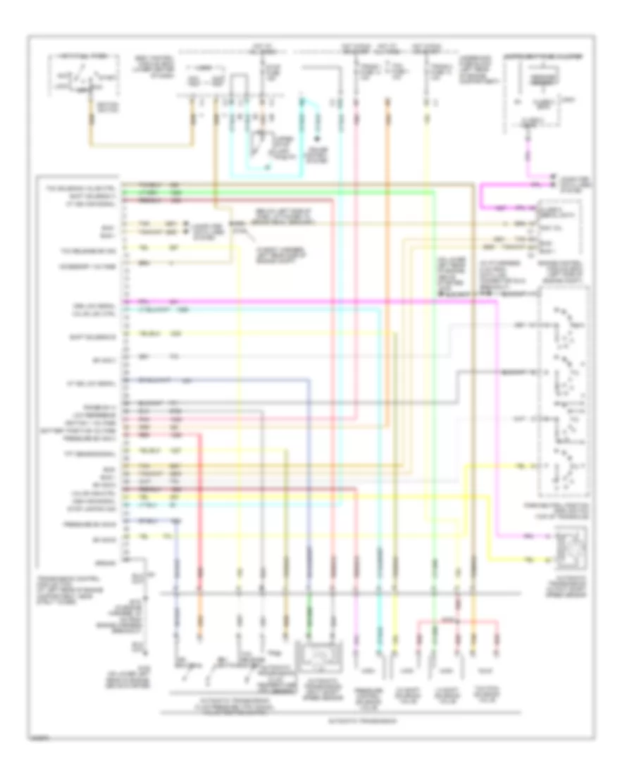
A/T Wiring Diagram for Saturn Ion 3 2005
List of elements for A/T Wiring Diagram for Saturn Ion 3 2005:
- (below left side of dash, attached to brake pedal bracket)
- (in body harness, left rear side of engine compt)
- (in i/p harness, 5 cm from data link connector (dlc) breakout) s175
- (on lower left rear of engine, above starter)
- 1-2 shift solenoid valve
- 2-3 shift solenoid valve
- Acc
- Acc vol
- Accessory voltage
- At iss high signal
- At iss low signal
- Automatic transmission
- Automatic transmission fluid pressure (tfp) manual valve position switch
- Automatic transmission fluid temperature (tft) sensor
- Automatic transmission input shaft speed sensor
- Automatic transmission output shaft speed sensor
- Battery positive voltage
- Body control module (bcm) (lower center of dash)
- Bus +
- Bus -
- Bus-
- Class 2 (ecm)
- Class 2 data
- Class 2 serial data
- Computer data lines system
- Cruise control system
- Dr switch
- E10
- Engine control module (ecm) (left side of engine compt)
- G105
- G105 (on lower left rear of engine, above starter)
- Ground
- Hot at all times
- Hot in run or start
- Ignition 1 voltage
- Ignition switch
- Instrument panel cluster
- Lock
- Logic
- Low reference
- Message center
- Off
- Oss high signal
- Oss low signal
- Park/neutral position (pnp) switch (top of transaxle)
- Pnk
- Pressure control solenoid valve
- Pressure sw sig b
- Pressure sw sig c
- Range sw a
- Red
- Rev switch
- Run
- S103
- S104
- S175 (in engine harness, 35 cm from engine harness breakout)
- Shift solenoid a
- Shift solenoid b
- Start
- Stop fuse 15a
- Stop lamp sw sig
- Sw sig b
- Sw sig c
- Sw sig d
- Tan
- Tcc pwm solenoid valve
- Tcc release sw sig
- Tcc release switch
- Tcc solenoid valve ctrl
- Tcm fuse 1 10a
- Tft sensor signal
- Trans 1 fuse 14 10a
- Trans 2 fuse 13 10a
- Transmission control module (tcm) (at left rear of engine compartment, near strut tower)
- Underhood fuse block (left rear of engine compartment)
- Upper stop lamp switch
- Valve high ctrl
- Valve low ctrl
 English