AIR CONDITIONING
A/C Wiring Diagram for Mazda B2300 1997

List of elements for A/C Wiring Diagram for Mazda B2300 1997:
- 7.5a
- A/c clutch diode
- A/c clutch field coil
- A/c cycling switch (right rear of engine compartment, on accumulator)
- A/c pressure switch (left front of engine on a/c line)
- A/c-heater control assembly
- Blend door actuator (behind right side of i/p)
- Blower motor
- Blower motor relay (in relay box 2)
- Blower motor resistor assembly (right rear of engine comparment)
- Blower switch
- C 1995 vftc
- Def
- Engine compartment fuse/relay box
- Flr
- Flr/def
- Fuse 15a
- Fuse 40a
- Fuse 6
- Fuse 7.5a
- G-231
- G-232
- G-233
- G-234
- G102 (top center of left fender apron)
- Hot at all times
- Hot in run
- I/p fuse panel
- Illumi- nation
- Interior lights system
- Max
- Norm
- Off
- Pan/flr
- Panel
- Pcm power relay
- Powertrain control module (right rear of engine compartment, through safety wall)
- Red
- Solid state
- Wide open throttle cutoff relay (in engine compartment fuse/relay box)
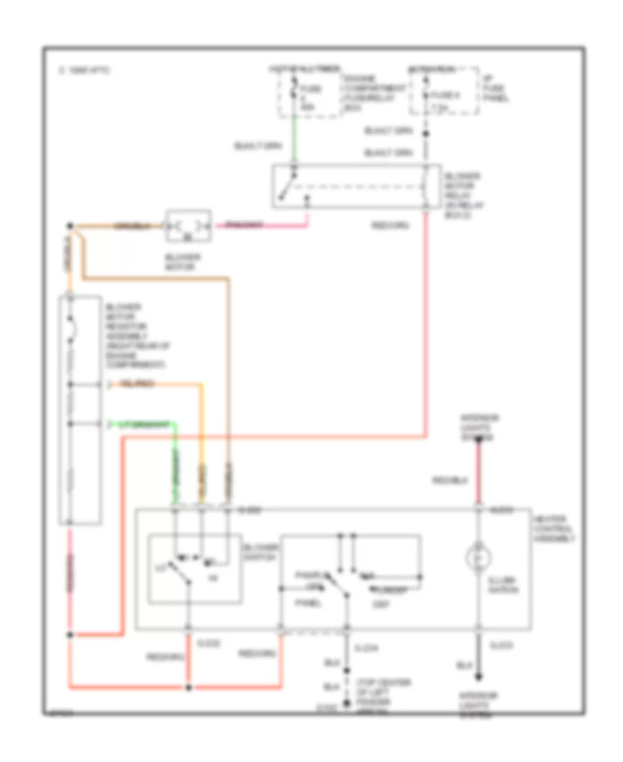
Heater Wiring Diagram for Mazda B2300 1997
List of elements for Heater Wiring Diagram for Mazda B2300 1997:
- (top center of left fender apron)
- 1995 vftc c
- 7.5a
- Blower motor
- Blower motor relay (in relay box 2)
- Blower motor resistor assembly (right rear of engine comparment)
- Blower switch
- Def
- Engine compartment fuse/relay box
- Flr
- Flr/def
- Fuse 40a
- Fuse 6
- G-232
- G-233
- G-234
- G102
- Heater control assembly
- Hot at all times
- Hot in run
- I/p fuse panel
- Illumi- nation
- Interior lights system
- Off
- Pan/flr
- Panel
 English