AIR CONDITIONING
2.4L
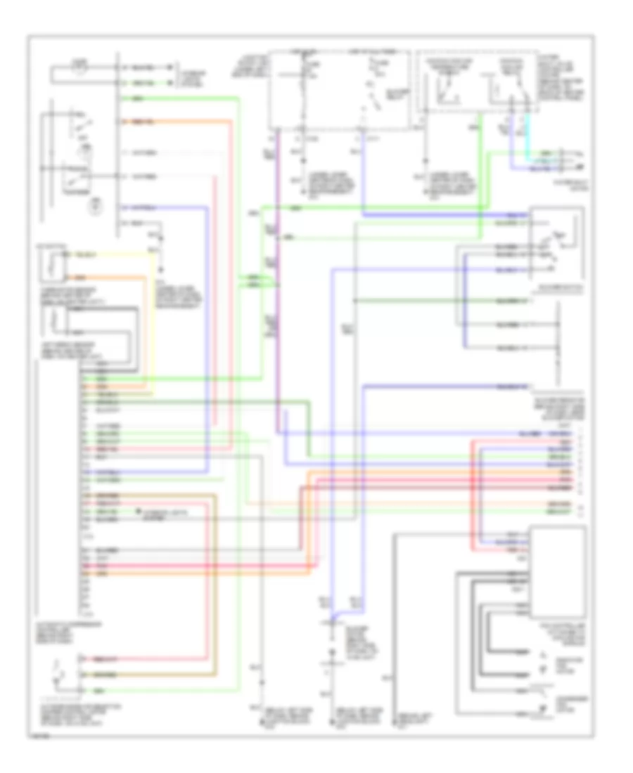
2.4L, Manual A/C Wiring Diagram (1 of 2) for Mitsubishi Eclipse GT 2004

List of elements for 2.4L, Manual A/C Wiring Diagram (1 of 2) for Mitsubishi Eclipse GT 2004:
- (behind left headlight) g11
- (below left side of dash, behind junction block) g15
- (below left side of of dash, behind junction block) g15
- (under lower center of dash, on right center reinforcement)
- (under lower center of dash, on right center reinforcement) g14
- A/c switch
- A30
- A30-1
- Air thermo sensor (behind center of dash, on heater unit)
- Automatic compressor controller (behind right side of dash)
- Blower motor (behind right side of dash on hvac unit)
- Blower relay
- Blower resistor (behind right side of dash, near blower motor)
- Blower switch
- C108
- C111
- Condenser fan motor
- Fan controller (attached to cooling fan shroud)
- Fuse 30a
- Fuse 7.5a
- G14
- G14 (under lower center of dash, on right center reinforcement)
- Hot at all times
- Hot in on
- Illum
- Ind
- Inside
- Interior lights system
- Junction block (j/b) (under left end of dash)
- Maximum cooling relay
- Maximum cooling temperature switch
- Nca
- Off
- Outside
- Outside/inside air selection damper control motor (behind right side of dash, 0n hvac unit)
- Radiator fan motor
- Red
- Thermistor sensor (behind center of dash, on heater unit)
- Water shut motor
- Water shut valve controller (coupe) (behind center of dash, on back of heater control panel)
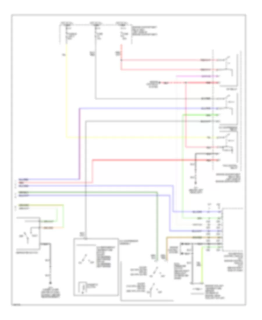
2.4L, Manual A/C Wiring Diagram (2 of 2) for Mitsubishi Eclipse GT 2004
List of elements for 2.4L, Manual A/C Wiring Diagram (2 of 2) for Mitsubishi Eclipse GT 2004:
- A/c compressor assembly
- A/c compressor relay
- A/c refrigerant temperature switch (on-off: 155 degrees centigrade) (off-on: 125 degrees centigrade)
- A/t
- C49
- C50
- C53
- C54
- C57
- C60
- Def
- Defroster switch
- Dual pressure switch (behind right headlight, on receiver drier)
- Engine compartment relay box (left side of engine compartment)
- Engine control system
- Engine controls system
- Engine coolant temperature sensor (on rear of engine, near coolant outlet)
- Fan control relay
- Foot
- Fuse 10a
- Fuse 20a
- Fusible link 2 50a
- G11 (behind left headlight)
- G14 (under lower center of dash, on right center reinforcement)
- Hot at all times
- M/t
- Magnetic clutch
- Mfi relay
- Off
- On-off: 200 kpa (28 psi) off-on: 220 kpa (32 psi)
- On-off: 3140 kpa (455 psi) off-on: 2550 kpa (370 psi)
- Powertrain control module (a/t) engine control module (m/t) (behind right side of dash)
- Red
3.0L
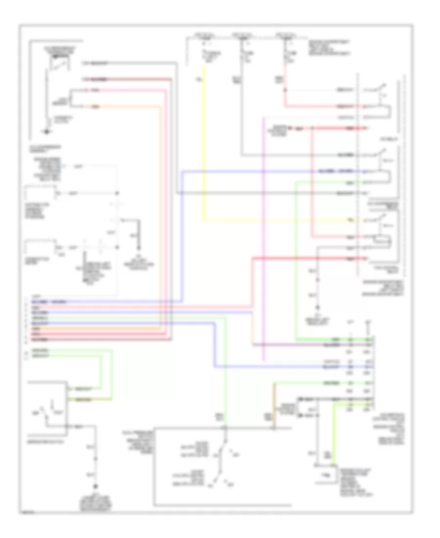
3.0L, Manual A/C Wiring Diagram (1 of 2) for Mitsubishi Eclipse GT 2004
List of elements for 3.0L, Manual A/C Wiring Diagram (1 of 2) for Mitsubishi Eclipse GT 2004:
- (behind left headlight) g11
- (below left side of dash, behind junction block) g15
- (under lower center of dash, on right center reinforcement) g14
- A/c switch
- A30
- A30-1
- Air thermo sensor (behind center of dash, on heater unit)
- Automatic compressor controller (behind right side of dash)
- Blower motor (behind right side of dash, on
- Blower relay
- Blower resistor (behind right side of dash, near blower motor)
- Blower switch
- C108
- C111
- C12
- C13
- Center of dash, on right center reinforcement) g14
- Condenser fan motor
- Fan controller (attached to cooling fan shroud)
- Fuse 30a
- Fuse 7.5a
- G14 (under lower center of dash, on right center reinforcement)
- Hot at all times
- Hot in on
- Hvac unit)
- Illum
- Ind
- Inside
- Interior lights system
- Junction block (j/b) (under left end of dash)
- Maximum cooling relay
- Maximum cooling temperature switch
- Nca
- Off
- Outside
- Outside/inside air selection damper control motor (behind right side of dash, on hvac unit)
- Pnk
- Radiator fan motor
- Red
- Thermistor sensor (behind center of dash, on heater unity)
- Water shut motor
- Water shut valve controller (coupe) (behind center of dash, on back of heater control panel)
3.0L, Manual A/C Wiring Diagram (2 of 2) for Mitsubishi Eclipse GT 2004
List of elements for 3.0L, Manual A/C Wiring Diagram (2 of 2) for Mitsubishi Eclipse GT 2004:
- A/c compressor assembly
- A/c compressor relay
- A/c refrigerant temperature sensor
- A/t
- Behind junction block) g15
- C42
- C51
- C52
- C55
- C58
- C59
- C62
- Combination meter
- Def
- Defroster switch
- Distributor assembly (on rear of engine)
- Dual pressure switch (behind right headlight, on receiver drier)
- Engine compartment relay box (left side of engine compartment)
- Engine controls system
- Engine coolant temperature sensor (on rear center of engine, near coolant outlet)
- Engine speed detection connector (in engine compartment relay box)
- Fan control relay
- Foot
- Fuse 10a
- Fuse 20a
- Fusible link 2 50a
- G11 (behind left headlight)
- G14 (under lower center of dash, on right center reinforcement)
- G4 (on left rear of intake manifold)
- Hot at all times
- Lock sensor
- M/t
- Magnetic clutch
- Mfi relay
- Off
- On-off: 200 kpa (28 psi) off-on: 220 kpa (32 psi)
- On-off: 3140 kpa (455 psi) off-on: 2550 kpa (370 psi)
- Pnk
- Powertrain control module (a/t) engine control module (m/t) (behind right side of dash)
- Red