AIR CONDITIONING
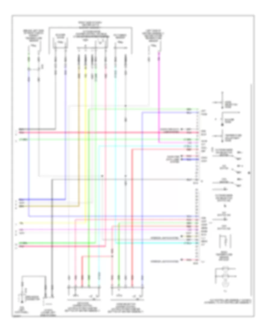
Manual A/C Wiring Diagram (1 of 3) for Mitsubishi i-MiEV ES 2012

List of elements for Manual A/C Wiring Diagram (1 of 3) for Mitsubishi i-MiEV ES 2012:
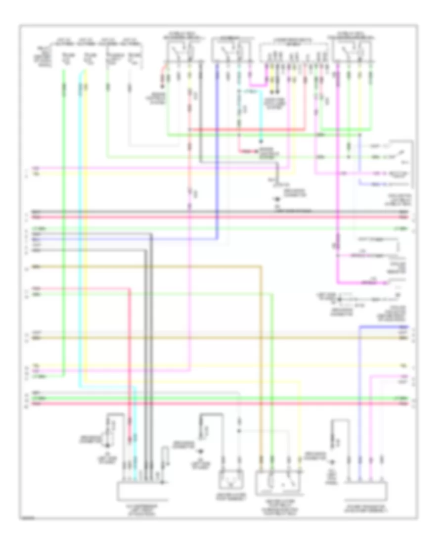
Manual A/C Wiring Diagram (2 of 3) for Mitsubishi i-MiEV ES 2012
List of elements for Manual A/C Wiring Diagram (2 of 3) for Mitsubishi i-MiEV ES 2012:
Manual A/C Wiring Diagram (3 of 3) for Mitsubishi i-MiEV ES 2012
List of elements for Manual A/C Wiring Diagram (3 of 3) for Mitsubishi i-MiEV ES 2012: