AIR CONDITIONING
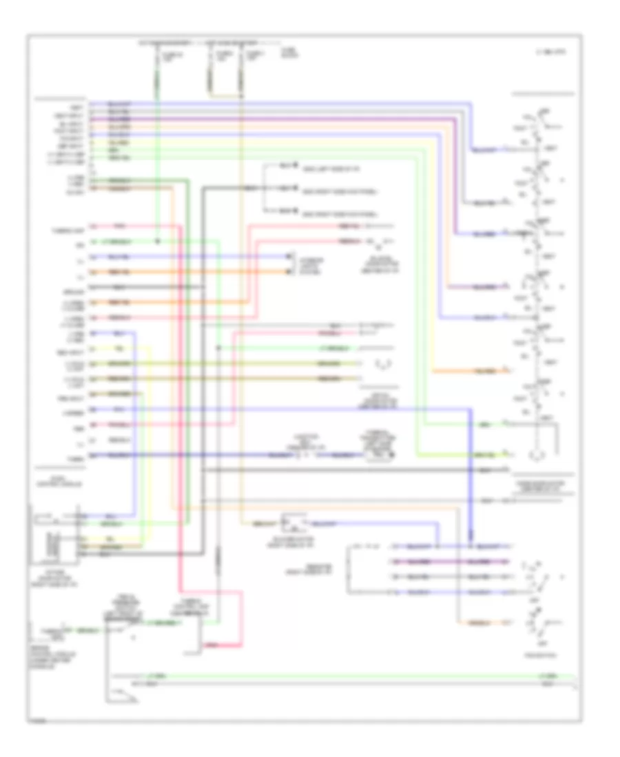
Air Conditioning Wiring Diagrams, Auto A/C (1 of 2) for Nissan Maxima GXE 1995

List of elements for Air Conditioning Wiring Diagrams, Auto A/C (1 of 2) for Nissan Maxima GXE 1995:
- (1996) (1995)
- (center of i/p)
- (left rear of engine)
- (left side
- (right de-
- (right side kick panel)
- (right side of i/p)
- +5v
- 11s
- 14j 10k
- 1994 vftc c
- A/mix actr
- A/mix pbr
- Air mix door motor
- Amb sens
- Ambient sensor (center front
- Auto amp
- B/l
- B/l actr
- Bi-level door motor
- Blower motor
- Comp
- Def
- Engine control module (below center console)
- F/d
- Fan control amp
- Fan f/b
- Fan gate
- Fascia)
- Ficd
- Foot
- Froster grille)
- Fuse 15a
- Fuse 16 fuse 30 7.5a 10a
- Fuse block
- G202
- G203
- Hot in on
- I/p)
- Ign
- In vehicle sensor (left side
- Incar sens
- Intake actr
- Intake code 1
- Intake code 2
- Intake code 3
- Intake code 4
- Intake door motor
- Intake sens
- Intake sensor (front
- Interior lights system
- K/d clk
- K/d r
- K/d t
- Mode actr
- Mode code 1
- Mode code 2
- Mode code 3
- Mode code 4
- Mode door motor (center of i/p)
- Of console)
- Of i/p)
- Or start
- Pnk
- Position switch
- Push control unit (center of i/p)
- Sens gnd
- Sunload sensor
- Thermal transmitter
- Thermo amp
- Triple pressure switch (left front of engine compt)
- Vent
- W/t sens
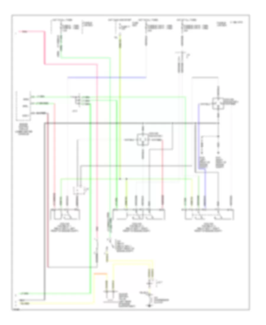
Air Conditioning Wiring Diagrams, Auto A/C (2 of 2) for Nissan Maxima GXE 1995
List of elements for Air Conditioning Wiring Diagrams, Auto A/C (2 of 2) for Nissan Maxima GXE 1995:
- (1995)
- (1996)
- (1996) (1995)
- 16l
- 1994 vftc c
- A/c compressor clutch
- A/c relay (relay box 1, right front of engine compt)
- Acrly
- Cooling fan motor 1
- Cooling fan motor 2
- Cooling fan relay 1 (relay box 2, left front of engine compt)
- Cooling fan relay 2 (relay box 1, right front of engine compt)
- Cooling fan relay 3 (relay box 1, right front of engine compt)
- Engine control module (under center console)
- Fuse 17 10a
- Fuse 61 fuse 56 7.5a
- Fuse box
- Fusible link box
- Fusible link d fusible link h 30a
- Fusible link e fusible link g 30a
- G100 (left front of engine compt)
- G101 (right front of engine compt)
- Hot at all times
- Hot in on and start
- Idle air control valve (left rear of engine compartment)
- J/c
- J/c 3
- J/c 7
- Pnk
- Rfrh
- Rfrl
Air Conditioning Wiring Diagrams, Manual A/C (1 of 2) for Nissan Maxima GXE 1995
List of elements for Air Conditioning Wiring Diagrams, Manual A/C (1 of 2) for Nissan Maxima GXE 1995:
- (+) cold (-) hot
- (+) fre (-) rec
- (+) open (-) close
- (+) vent/(-) def
- (-) cold (+) hot
- (-) fre (+) rec
- (-) open (+) close
- (-) vent/(+) def
- (center of i/p)
- (left side of i/p) g202
- (right side kick panel) g203
- (right side of i/p)
- 1994 vftc c
- 4 speed
- A/c sw
- Air mix door motor
- B/l
- B/l input
- Bi-level door motor
- Blower motor
- Console)
- Def
- Def input
- Engine control module (under center
- F/d
- F/d input
- Fan switch
- Foot
- Foot input
- Fre input
- Fuse 2 15a
- Fuse 3 15a
- Fuse 30 10a
- Fuse block
- Ground
- Hot in on or start
- Ign
- Ill
- Intake door motor
- Interior lights system
- Junction box (center of i/p)
- Mode door motor (center of i/p)
- Off
- Pbr
- Pnk
- Push control module
- Rec input
- Resistor
- Switch position
- Therm
- Thermal transmitter (left side of engine)
- Thermo amp
- Thermo control amp
- Triple pressure switch (left front of engine compt)
- Vent
- Vent input
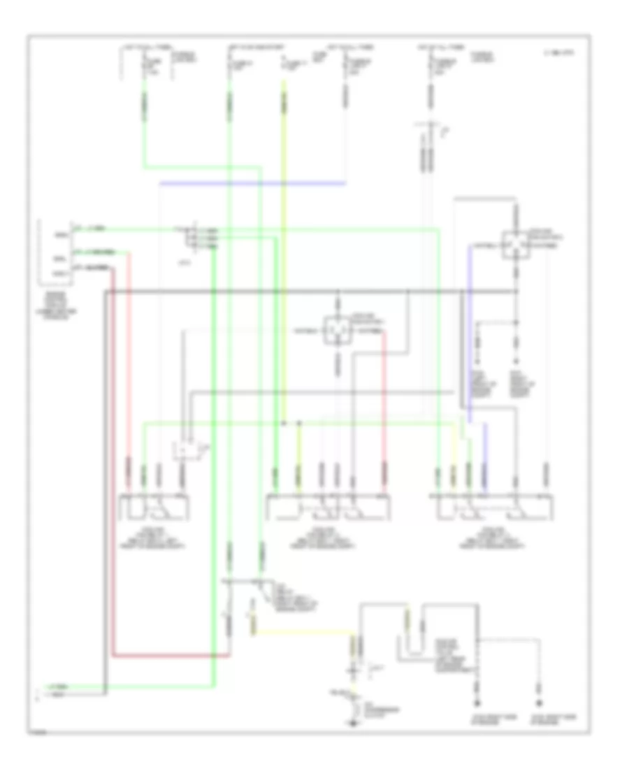
Air Conditioning Wiring Diagrams, Manual A/C (2 of 2) for Nissan Maxima GXE 1995
List of elements for Air Conditioning Wiring Diagrams, Manual A/C (2 of 2) for Nissan Maxima GXE 1995:
- (right side g120
- 1994 vftc c
- A/c compressor clutch
- A/c relay (relay box 1, right front of engine compt)
- Acrly
- Cooling fan motor 1
- Cooling fan motor 2
- Cooling fan relay 1 (relay box 2, left front of engine compt)
- Cooling fan relay 2 (relay box 1, right front of engine compt)
- Cooling fan relay 3 (relay box 1, right front of engine compt)
- Engine control module (under center console)
- Fuse 7.5a
- Fuse 17 10a
- Fuse 31 10a
- Fuse box
- Fusible link g 30a
- Fusible link h 30a
- Fusible link box
- G100 (left front of engine compt)
- G101 (right front of engine compt)
- Hot at all times
- Hot in on and start
- Idle air control valve (left rear of engine compartment)
- J/c
- J/c 3
- J/c 7
- Of engine)
- Rfrh
- Rfrl