ENGINE PERFORMANCE
3.0L
3.0L, Engine Performance Wiring Diagrams (1 of 2) for Nissan Maxima GXE 1995

List of elements for 3.0L, Engine Performance Wiring Diagrams (1 of 2) for Nissan Maxima GXE 1995:
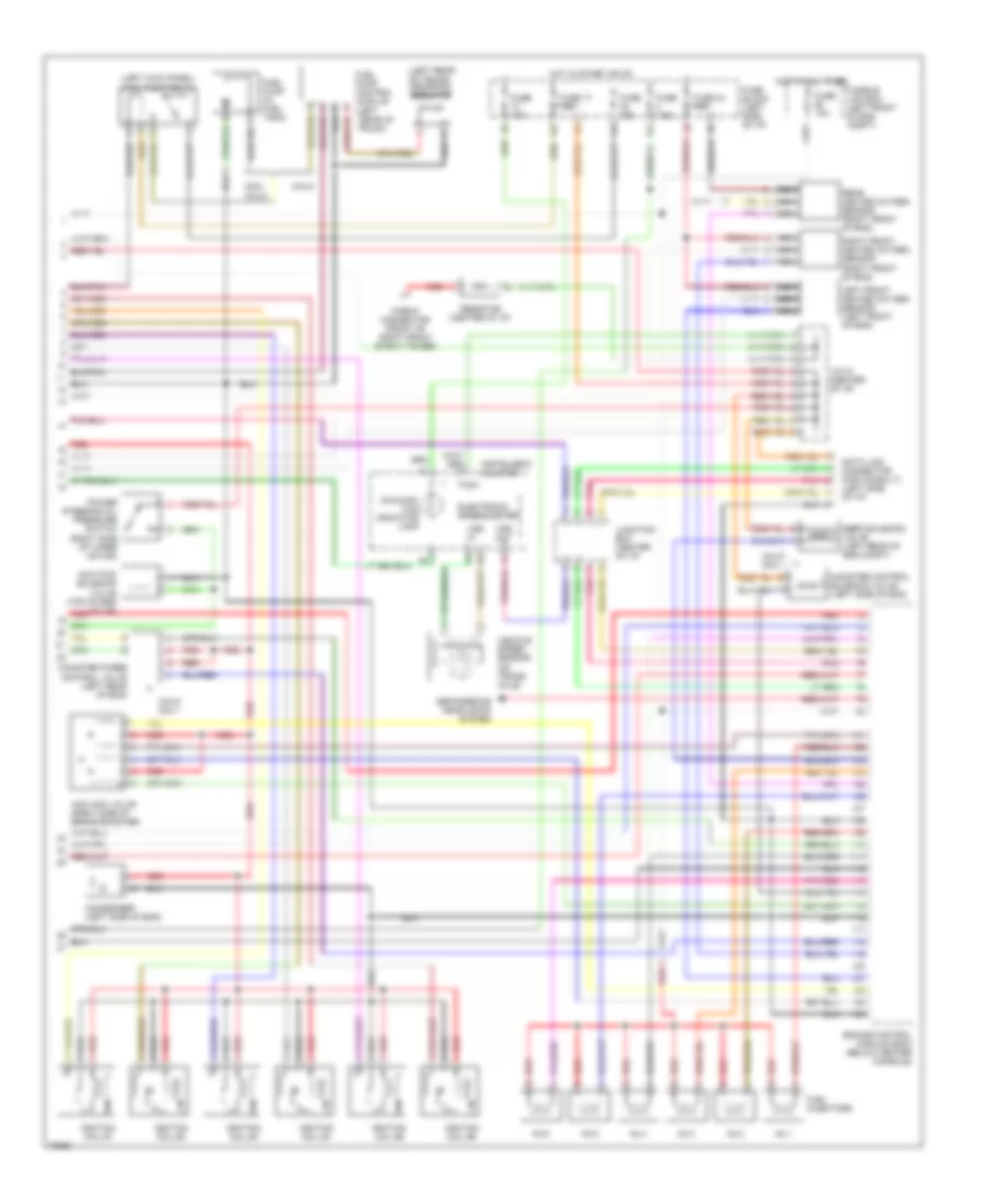
3.0L, Engine Performance Wiring Diagrams (2 of 2) for Nissan Maxima GXE 1995
List of elements for 3.0L, Engine Performance Wiring Diagrams (2 of 2) for Nissan Maxima GXE 1995: