AIR CONDITIONING
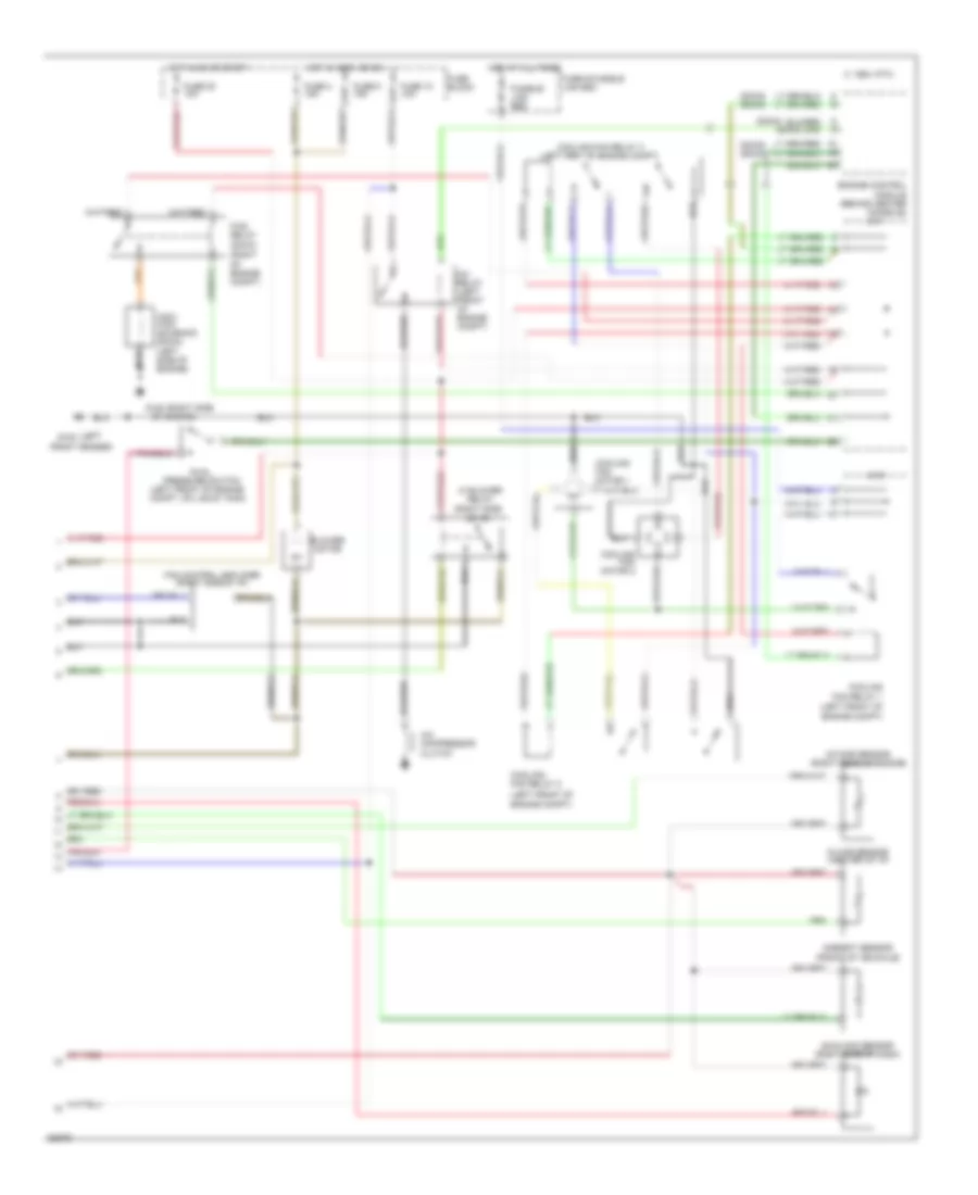
Air Conditioning Wiring Diagrams, Auto A/C (1 of 2) for Nissan Maxima SE 1994

List of elements for Air Conditioning Wiring Diagrams, Auto A/C (1 of 2) for Nissan Maxima SE 1994:
- (below g300
- (center of i/p)
- Air mix door motor (center of i/p)
- Auto amp
- B/l
- Def
- Engine control module (behind center console)
- F/d
- Foot
- Fresh vent control illumination
- Fuse 23 10a
- Fuse block
- Hot at all times
- Intake door motor (attached to front of heater unit)
- Interior lights system
- Left front seat)
- Mode door motor (center of i/p)
- Pnk
- Pos sw
- Thermistor
- Thermo control amp (right side of i/p)
- Vent
- Water cock solenoid (center rear of engine)
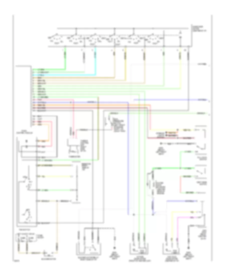
Air Conditioning Wiring Diagrams, Auto A/C (2 of 2) for Nissan Maxima SE 1994
List of elements for Air Conditioning Wiring Diagrams, Auto A/C (2 of 2) for Nissan Maxima SE 1994:
- (dohc)
- (dohc) (sohc)
- (front of vehichle)
- (left front of engine compt)
- (left front of engine compt, on liquid tank)
- (left g100
- (right of engine compt)
- (sohc)
- 1994 vftc c
- A/c compressor clutch
- A/c relay (left front of engine compt)
- Ambient sensor
- Blower motor
- Cooling fan motor 1
- Cooling fan motor 2
- Cooling fan relay 1
- Cooling fan relay 2
- Cooling fan relay 3 (left frnt of engine compt)
- Dual pressure switch
- Engine control module (behind center console)
- Fan control amplifier (right side of i/p)
- Ficd relay
- Front fender)
- Fuse & fusible link box
- Fuse 10 10a
- Fuse 20 10a
- Fuse 4 15a
- Fuse 5 15a
- Fuse block
- Fusible link red
- G120 (right side
- Hi blower relay (right side
- Hot at all times
- Hot in accy or on
- Hot in on or start
- Iacv- ficd solenoid (dohc) (left side of engine)
- In car sensor (center of i/p)
- Intake sensor (right rear of engine)
- J/c 1
- J/c 2
- Of engine)
- Of i/p)
- Sunload sensor (right side of dash)
Air Conditioning Wiring Diagrams, Manual A/C (1 of 2) for Nissan Maxima SE 1994
List of elements for Air Conditioning Wiring Diagrams, Manual A/C (1 of 2) for Nissan Maxima SE 1994:
- (below left front seat)
- (center rear of engine)
- B/l
- Blower motor
- Blower motor relay (right side of i/p)
- Def
- Dual pressure switch (left front of engine compt, on liquid tank)
- F/d
- Fan switch
- Foot
- Full cold switch
- Fuse 15a
- Fuse block
- G300
- Hot in accy or on
- Intake door motor (front of heater unit)
- Interior lights system
- Max cold door motor (center of i/p)
- Max cold relay (center
- Mode door motor (center of i/p)
- Of i/p)
- Off
- Pnk
- Pos sw
- Push control module
- Red
- Resistor (right side of i/p)
- Thermister
- Thermo control amp (right side of i/p)
- Vent
- Vent mode switch
- Water cock solenoid
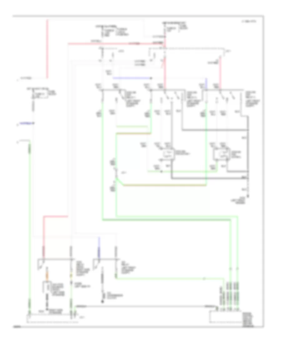
Air Conditioning Wiring Diagrams, Manual A/C (2 of 2) for Nissan Maxima SE 1994
List of elements for Air Conditioning Wiring Diagrams, Manual A/C (2 of 2) for Nissan Maxima SE 1994:
- (dohc)
- (left front of engine compt)
- (right side of engine)
- (sohc)
- 1994 vftc c
- A/c compressor clutch
- A/c relay
- Compt)
- Cooling fan motor 1
- Cooling fan motor 2
- Cooling fan relay 1
- Cooling fan relay 2
- Cooling fan relay 3
- Diode (left side i/p)
- Engine control module (behind center console)
- Ficd relay (dohc) (right side of engine
- Fuse 10 10a
- Fuse 20 10a
- Fuse block
- Fusible link & fuse box
- Fusible link red
- G100 (left front fender)
- G120
- Hot at all times
- Hot in accy or on
- Hot in on or start
- Iacv-ficd solenoid (dohc) (left side of engine)
- J/c 1
- J/c 2