INSTRUMENT CLUSTER
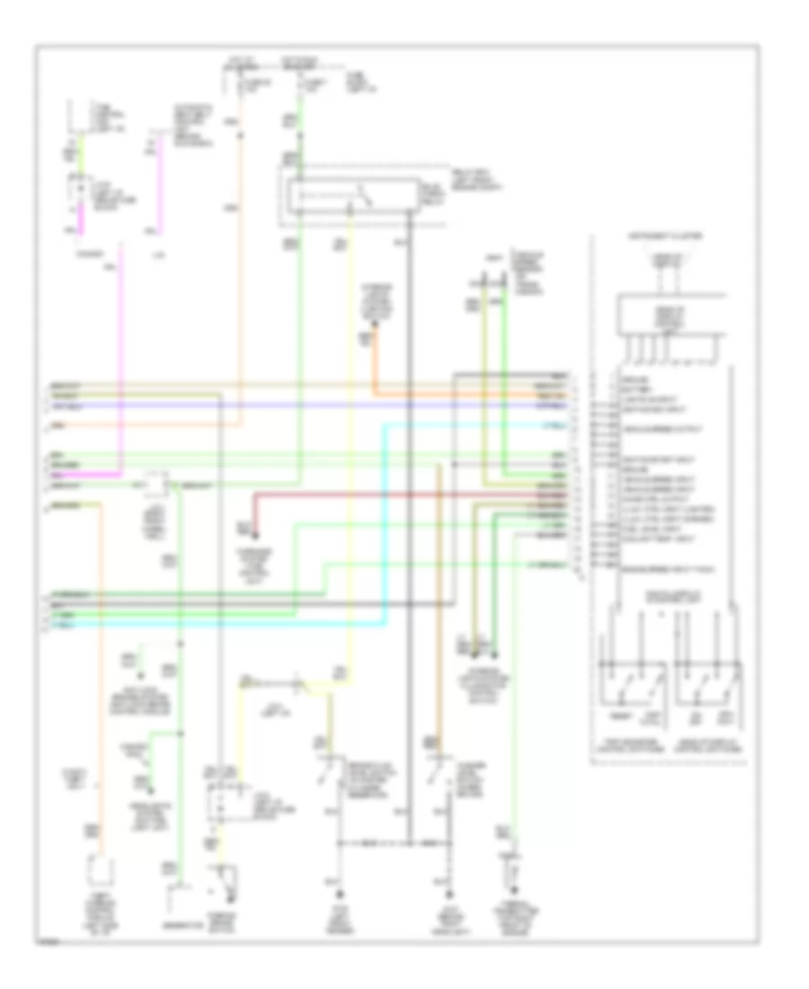
Instrument Cluster Wiring Diagram, with Head-Up Display (1 of 2) for Nissan Maxima SE 1994

List of elements for Instrument Cluster Wiring Diagram, with Head-Up Display (1 of 2) for Nissan Maxima SE 1994:
- (actuator)
- (mil)
- (time control unit)
- A-1
- A-10
- A-11
- A-12
- A-13
- A-15
- A-16
- A-17
- A-2
- A-3
- A-4
- A-5
- A-6
- A-7
- A-8
- A-9
- A/t control unit (behind center console)
- A/t only
- Abs control module (in trunk, below right rear shelf)
- Abs ind.
- Air bag control module (below center console)
- Air bag ind.
- Anti-lock
- Ascd control module (bottom of steering column)
- B-16
- B-18
- B-19
- B-20
- B-21
- B-22
- B-23
- B-24
- B-25
- B-26
- Bat
- Brake ind.
- Brakes system
- C-28
- C-29
- C-31
- Charge ind.
- Check connector (left i/p)
- Check engine ind.
- Chime
- Clock
- Cruise ind.
- Door ind.
- Eccs control module (behind center console)
- Exterior
- Fuel ind.
- Fuel tank gauge unit (in fuel tank)
- Fuse 10 10a
- Fuse 21 10a
- Fuse 23 10a
- Fuse block (left i/p)
- G200 (left kick panel)
- G201 (right side of i/p)
- Gnd
- Headlights system (lighting switch)
- Hi beam ind.
- Hot at all times
- Hot in run or acc
- Hot in run or start
- Ign
- Illum- ination
- Instrument cluster
- Interior lights system (door switches)
- Interior lights system (illumination control switch)
- Left turn ind.
- Lights system (turn signal
- Nca
- O/d off ind.
- Oil ind.
- Oil pressure switch
- Overdrive control switch
- Right turn ind.
- Seat belt ind.
- Security ind.
- Switch)
- Warnings system
- Washer ind.
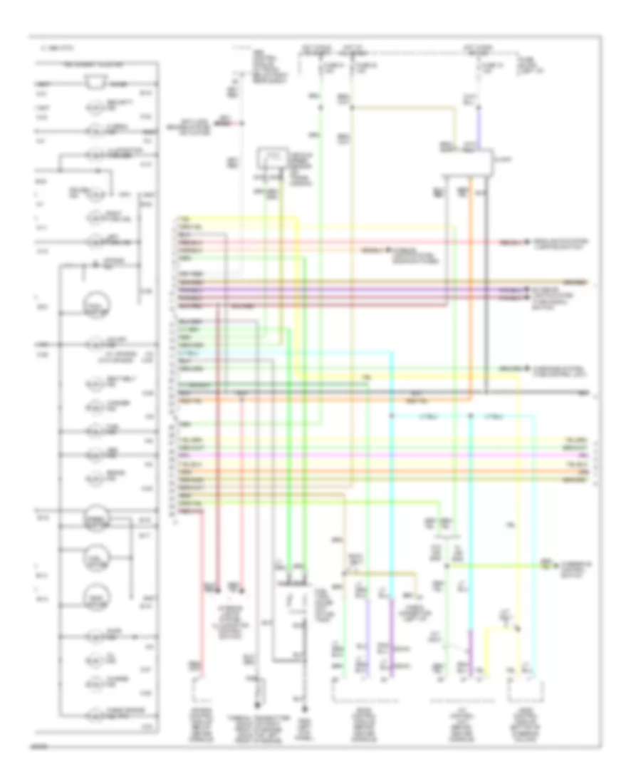
Instrument Cluster Wiring Diagram, with Head-Up Display (2 of 2) for Nissan Maxima SE 1994
List of elements for Instrument Cluster Wiring Diagram, with Head-Up Display (2 of 2) for Nissan Maxima SE 1994:
- (in master
- (left i/p)
- (right front wheel- well)
- Anti-lock brakes system (anti-lock brake control module)
- Automatic seat belt control unit (behind glove box)
- Battery
- Brake fluid level switch
- Bulb check relay
- Canada
- Canada only
- Chime ctrl output
- Coolant temp. input
- Cylinder
- Digital display & control unit
- Engine speed input (tach)
- Fuel level input
- Fuse 25 10a
- Fuse 7 10a
- Fuse block (left i/p)
- G100 (left front fender)
- G107 (behind right headlight)
- Generator
- Ground
- Head-up display
- Head-up display control switches
- Head-up display control unit
- Headlights system (daytime light unit)
- Hot at all times
- Hot in run or start
- Ignition/acc input
- Ignition/start input
- Illum. ctrl input (darken)
- Illum. ctrl input (lighten)
- Instrument cluster
- Interior lights system (illumination control switch)
- Interior lights system (lighting switch)
- J/c-1
- J/c-4
- J/c-8 (left i/p, above fuse block)
- J/c-9 (left i/p, above fuse block)
- Lights on input
- Mph- km/h
- Nca
- On- off
- Parking brake switch
- Relay box (left front engine compt)
- Reservoir)
- Reset
- Theft warning control module (left side of i/p)
- Thermal transmitter (top right front of engine)
- Time control unit (left i/p)
- Trip odometer control switches
- Trip- total
- U.s.
- Vehicle speed input
- Vehicle speed output
- Vehicle speed sensor (on trans- mission)
- W/anti- theft only
- Warnings system (time control unit)
- Washer level switch (in res- ervoir)
Instrument Cluster Wiring Diagram, without Head-Up Display (1 of 2) for Nissan Maxima SE 1994
List of elements for Instrument Cluster Wiring Diagram, without Head-Up Display (1 of 2) for Nissan Maxima SE 1994:
- (actuator)
- (dohc)
- (door switches)
- (mil)
- (sohc)
- (w/ air bag)
- (w/o air bag)
- 1995 vftc c
- A-1
- A-10
- A-11
- A-12
- A-2
- A-3
- A-4
- A-5
- A-6
- A-8
- A-9
- A/t control unit (behind center console)
- A/t only
- Abs control module (in trunk, below right rear shelf)
- Abs ind.
- Air bag control module (below center console)
- Air bag ind.
- Anti-lock
- Ascd control module (bottom of steering column)
- B-13
- B-14
- B-15
- B-16
- B-17
- B-18
- B-19
- B-21
- B-22
- B-23
- Bat
- Brake ind.
- Brakes system
- C-25
- C-27
- C-28
- C-29
- C-30
- C-31
- C-32
- C-33
- C-34
- C-35
- C-36
- Charge ind.
- Check connector (left i/p)
- Check engine ind.
- Chime
- Clock
- Cruise ind.
- Door ind.
- Eccs control module (behind center console)
- Exterior lights system (turn signal switch)
- Fuel gauge
- Fuel ind.
- Fuel tank gauge unit (in fuel tank)
- Fuse 10 10a
- Fuse 21 10a
- Fuse 23 10a
- Fuse block (left i/p)
- G200 (left kick panel)
- Gnd
- Headlights system (lighting switch)
- Hi beam ind.
- Hot at all times
- Hot in run or acc
- Hot in run or start
- Ign
- Illumination (4 bulbs)
- Instrument cluster
- Interior
- Interior lights system (illumination control switch)
- Left turn ind.
- Lights system
- Nca
- O/d off ind.
- Oil ind.
- Overdrive control switch
- Right turn ind.
- Seat belt ind.
- Security ind.
- Sohc only
- Speed- ometer
- Tach- ometer
- Temp. gauge
- Thermal transmitter (sohc-top right front of engine) (dohc-top left front of engine)
- Vehicle speed sensor (on trans- mission)
- W/ air bag
- W/o air bag
- Warnings system (time control unit)
- Washer ind.
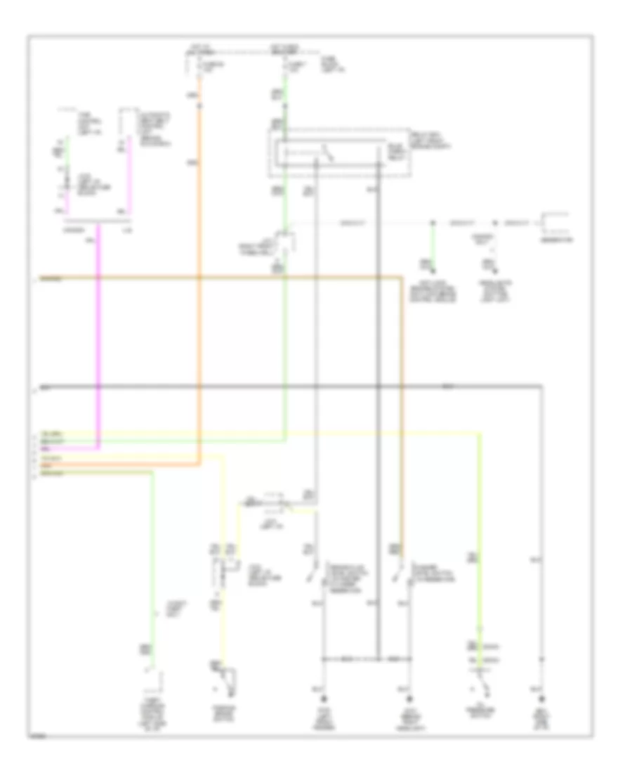
Instrument Cluster Wiring Diagram, without Head-Up Display (2 of 2) for Nissan Maxima SE 1994
List of elements for Instrument Cluster Wiring Diagram, without Head-Up Display (2 of 2) for Nissan Maxima SE 1994:
- (dohc)
- (in master
- (left i/p)
- (sohc)
- Anti-lock brakes system (anti-lock brake control module)
- Automatic seat belt control unit (behind glove box)
- Brake fluid level switch
- Bulb check relay
- Canada
- Canada only
- Cylinder
- Fuse 25 10a
- Fuse 7 10a
- Fuse block (left i/p)
- G100 (left front fender)
- G107 (behind right headlight)
- G201 (right side of i/p)
- Generator
- Headlights system (daytime light unit)
- Hot at all times
- Hot in run or start
- J/c-1 (right front wheelwell)
- J/c-4
- J/c-8 (left i/p, above fuse block)
- J/c-9 (left i/p, above fuse block)
- Level switch (in reservoir)
- Oil pressure switch
- Parking brake switch
- Relay box (left front engine compt)
- Reservoir)
- Theft only
- Theft warning control module (left side of i/p)
- Time control unit (left i/p)
- U.s.
- W/anti-
- Washer