ANTI-LOCK BRAKES
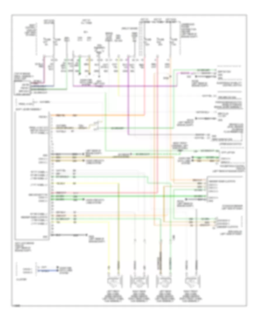
Anti-lock Brakes Wiring Diagram for Fiat 500c Abarth 2013
List of elements for Anti-lock Brakes Wiring Diagram for Fiat 500c Abarth 2013:
- (body front harness, left side of dash) s009
- (left rear of engine compt) g005
- (top of brake pedal assembly) stop lamp switch
- A/t
- A111
- A921
- Abs mod batt fd
- Abs/esp clstr fd
- Abs/esp snsr clstr fd
- Anti-lock brake module (left rear of engine compt)
- B(+)
- B134
- B20
- B25
- Body control module (left end of dash)
- Brake fluid level sensor (on brake fluid reservoir)
- Brake fluid level signal
- Brk flud lvl sw
- Brk sig 2
- C308
- Can b (+)
- Can b (-)
- Can bus (+)
- Can bus (-)
- Can c (+)
- Can c (-)
- Canc (+)
- Circuit board
- Cluster
- Computer data lines system
- D64
- D65
- Dynamics sensor (left end of dash)
- Electronic stability control switch
- Eps module (left side of dash)
- Esp sw sig
- Exterior lights system
- Fsd b(+)
- Fuse 20a
- Fuse 40a
- Fuse 5a
- Fuse 7.5a
- G005 (left rear of engine compt)
- G010a (left rear of engine compt)
- G010b (left rear of engine compt)
- G021 (left kick panel)
- Gnd
- Hot at all times
- Hot in on or start
- I028
- Ign rs
- L56
- Left front abs wheel speed sensor (left front wheel hub assembly)
- Left rear abs wheel speed sensor (left rear wheel hub assembly)
- Lt ft wheel (+)
- Lt ft wheel (-)
- Lt rr wheel (+)
- Lt rr wheel (-)
- M/t
- Parking brake switch (base of parking brake lever assembly)
- Pdc bus bar 3
- Perf mode sw sig
- Powertrain control module (left rear of engine compt)
- Prk brk sw sig
- Prndl hi sw
- Prndl hi sw (a/t) esp sw sig (m/t)
- Right front abs wheel speed sensor (right front wheel hub assembly)
- Right rear abs wheel speed sensor (right rear wheel hub assembly)
- Rt ft wheel (+)
- Rt ft wheel (-)
- Rt rr wheel (-)
- S026
- S52
- Shift lever assembly
- Stp lmp sig
- T824 (or b47)
- Underhood power distribution center (left rear of engine compt)
- Upper bank switch
- Z406
- Z905
 English