ANTI-LOCK BRAKES
Anti-lock Brakes Wiring Diagram for Mazda 2 Touring 2012
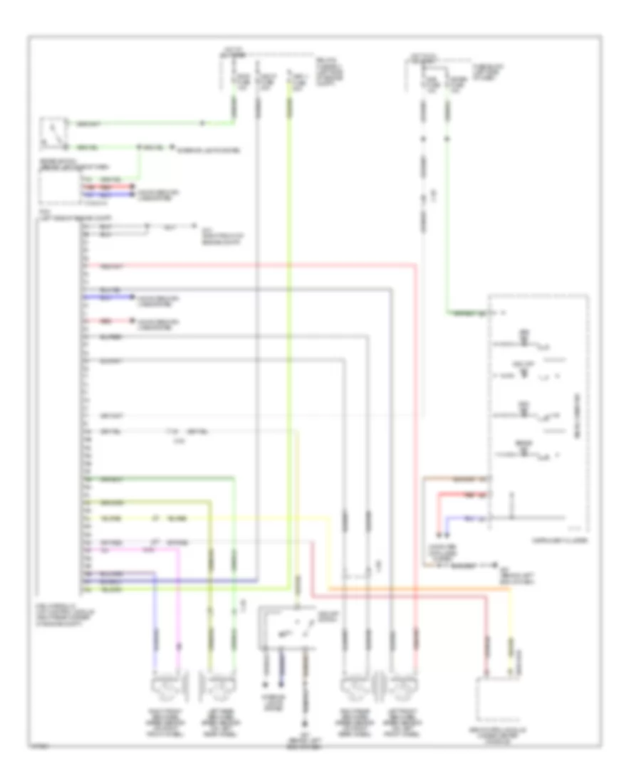
List of elements for Anti-lock Brakes Wiring Diagram for Mazda 2 Touring 2012:
- 0140-01a
- 0810-101b
- 1ae
- 1ai
- Abs ind
- Brake ind
- Brake switch (behind left side of dash)
- C-02
- C-03
- Computer data lines system
- Dsc hydraulic unit control module (right rear corner of engine compt)
- Dsc ind
- Dsc off ind
- Dsc off switch
- Dsc-p fuse 30a
- Dsc-v fuse 20a
- Exterior lights system
- Fuse block (left side of dash)
- G07 (behind left end of dash)
- G13 (right front of engine compt)
- Hot at all times
- Hot in on or start
- Ill
- Instrument cluster
- Interior lights system
- Left front abs wheel speed sensor (on left front wheel)
- Left rear abs wheel speed sensor (on left rear wheel)
- Meter fuse 10a
- Micro computer
- Pcm (left side of engine compt)
- Red
- Relay & fuse box (left side of engine compt)
- Right front abs wheel speed sensor (on right front wheel)
- Right rear abs wheel speed sensor (on right rear wheel)
- Sas control module (under center console)
- Sas fuse 10a
- Stop fuse 10a
 English