ANTI-LOCK BRAKES
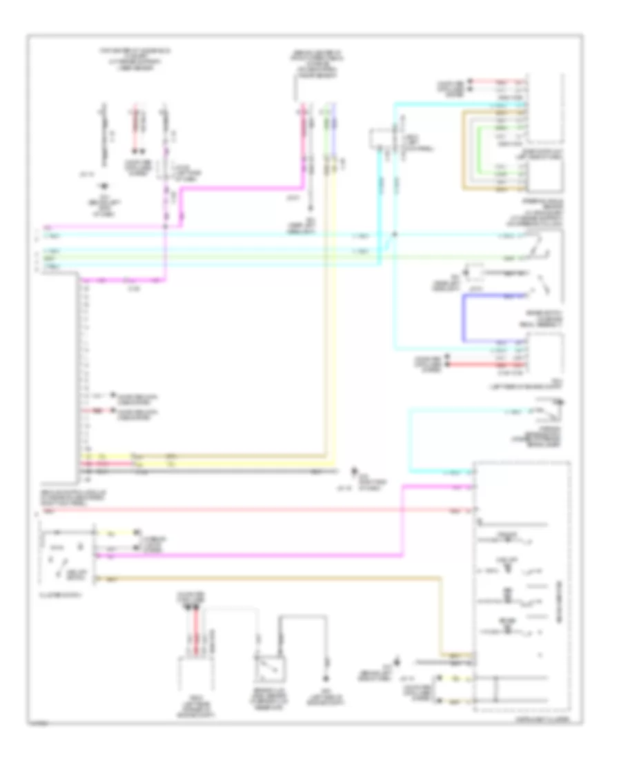
Anti-lock Brakes Wiring Diagram (1 of 2) for Mazda 3 Grand Touring 2014

List of elements for Anti-lock Brakes Wiring Diagram (1 of 2) for Mazda 3 Grand Touring 2014:
- (behind lower center of dash) j/c-39
- (on right front wheel hub assembly) right front abs wheel speed sensor
- 0940-102b
- 0940-102c
- 0940-102d
- Abs/dsc m fuse 50a
- Abs/dsc s fuse 30a
- Brake light relay
- Brake light unit (left "c" pillar)
- C-05
- C-52
- C-54
- C/u ig1 fuse 15a
- Computer data lines system
- Cruise system
- Dsc hu/cm (right side of engine compt)
- G03 (near right headlight)
- Hot at all times
- Hot w/ ig1 relay energized
- J/b-01 (left kick panel)
- Left front abs wheel speed sensor (on left front wheel hub assembly)
- Left rear abs wheel speed sensor (on left rear wheel hub assembly)
- Meter 1 fuse 10a
- Pnk
- Rbcm (w/ smart city brake support) (left side of luggage compt)
- Red
- Relay & fuse block (left rear of engine compt)
- Right rear abs wheel speed sensor (on right rear wheel hub assembly)
- Srs1 fuse 7.5a
- Stop fuse 10a
- Tan
- W/ radar
- W/o radar cruise system
Anti-lock Brakes Wiring Diagram (2 of 2) for Mazda 3 Grand Touring 2014
List of elements for Anti-lock Brakes Wiring Diagram (2 of 2) for Mazda 3 Grand Touring 2014:
- (behind center of front upper fascia) (w/ radar cruise system) radar sensor
- (top center of windshield) (w/ smart city brake support) laser sensor
- 0140-101b
- 0940-101b
- 0940-103a
- 0940-103b
- 2ak
- 2al
- Abs ind
- Brake fluid level sensor (in brake fluid reservoir)
- Brake ind
- Brake switch (on brake pedal assembly)
- C-03
- C-05
- C-12
- C-46
- C-52
- C-54
- C-55
- Cluster switch
- Computer data lines system
- Dsc ind
- Dsc off ind
- Dsc off switch
- Fbcm (left rear corner of engine compt)
- G01 (near left headlight)
- G02 (left side of engine compt)
- G10 (behind left side of dash)
- G16 (right end of dash)
- Instrument cluster
- Interior lights system
- J/b-01 (left kick panel)
- J/c-01
- J/c-10
- J/c-16
- J/c-35 (left side of dash)
- Microcomputer
- Parking brake switch (at base of parking brake lever)
- Pcm (left rear of engine compt)
- Pnk
- Red
- Start-stop unit (left side of dash)
- Steering angle sensor (w/ afs & smart city brake support) (on steering column)
- Vehicle control module (w/ radar cruise system) (right kick panel)