ANTI-LOCK BRAKES
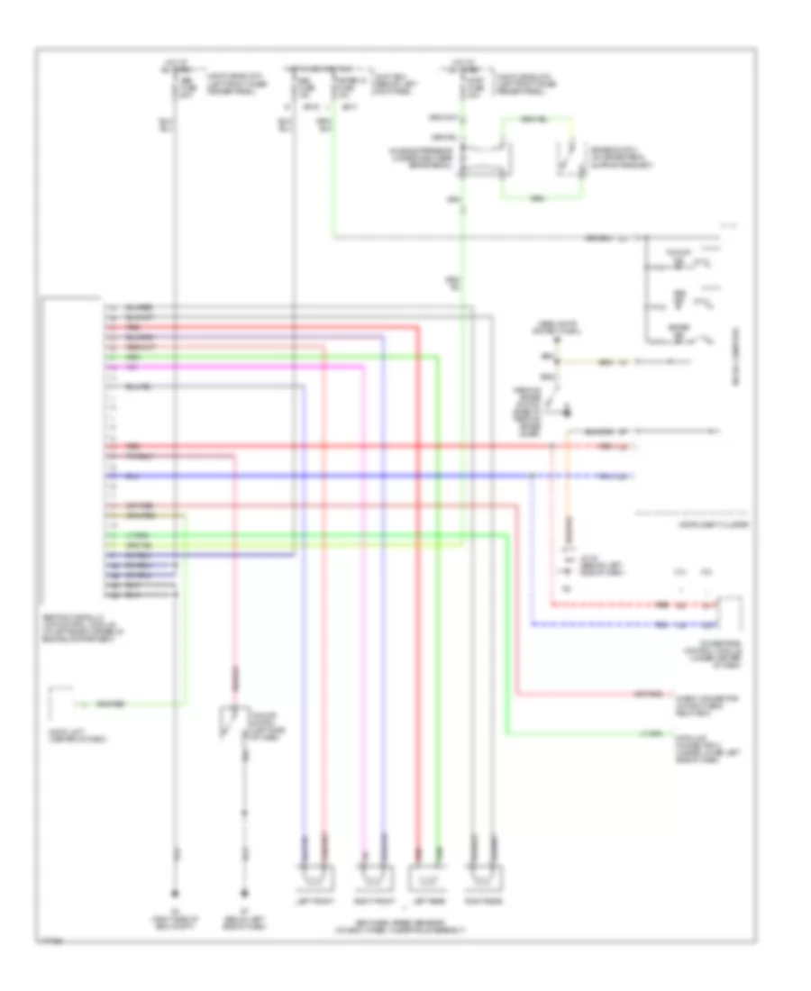
Anti-lock Brakes Wiring Diagram for Mazda 6 s 2003
List of elements for Anti-lock Brakes Wiring Diagram for Mazda 6 s 2003:
- (below left side of dash)
- (right side of eng compt)
- 2.3l
- 3.0l
- Abs fuse 60a
- Abs ind
- Abs wheel speed sensors (on each wheel hub/spindle assembly)
- Abs/tcs hydraulic unit/control module (at left rear corner of engine compartment)
- Audio unit (center of dash)
- Brake ind
- Brake switch (on brake pedal
- Check connector (in main fuse & relay box)
- Data link connector 2 (under lower left side of dash)
- Headlights system (w/drl)
- Hot at all times
- Hot in acc and run
- Instrument cluster
- Jb-01
- Jb-02
- Jc-02 (behind left side of dash)
- Joint box (behind left kick panel)
- Left front
- Left rear
- Main fuse block (left front inner fender panel)
- Meter ig fuse 15a
- Micro-computer
- Noise suppressor (under dash near brake pedal)
- Parking brake switch (base of parking brake lever)
- Powertrain control module (under center of dash)
- Red
- Right front
- Right rear
- Sas fuse 15a
- Stop fuse 20a
- Support bracket)
- Tcs off ind
- Tcs off switch (left side of dash)
 English