ANTI-LOCK BRAKES
Anti-lock Brakes Wiring Diagram for Mazda CX-5 Grand Touring 2013
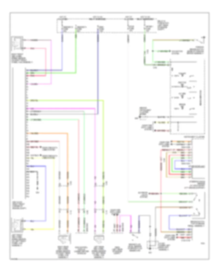
List of elements for Anti-lock Brakes Wiring Diagram for Mazda CX-5 Grand Touring 2013:
- (behind instrument cluster) j/c g09
- 0140-101b
- 0810-101c
- 0940-101b
- 0940-103a
- 0940-103b
- 2ak
- 2al
- 4w abs ind
- Abs/dsc m fuse 50a
- Abs/dsc s fuse 30a
- Brake fluid level sensor (in brake fluid reservoir)
- Brake ind
- Brake switch (top of brake pedal assembly)
- C-03
- C-04
- C-08
- C-14
- Computer data lines system
- Dsc hu/cm (right front corner of engine compt)
- Dsc/tcs ind
- Exterior lights system
- Fbcm (left rear of engine compt)
- G01
- G04
- G09
- Hot at all times
- Hot w/ ig1 relay energized
- Instrument cluster
- J/c g01 (under left headlight assembly)
- Left front abs wheel speed sensor (on left front wheel hub assembly)
- Left rear abs wheel speed sensor (on left rear wheel hub assembly)
- Meter 1 fuse 10a
- Microcomputer
- Navigation system
- Parking brake switch (base of parking brake assembly)
- Pcm
- Pnk
- Red
- Relay & fuse block (left rear of engine compt)
- Right front abs wheel speed sensor (on right front wheel hub assembly)
- Right rear abs wheel speed sensor (on right rear wheel hub assembly)
- Sas control module (under center console)
- Srs1 fuse 7.5a
- Start-stop unit
- Steering angle sensor (w/ afs & smart city brake support)
- Stop fuse 10a
- Tcs off
 English