ANTI-LOCK BRAKES
Anti-lock Brakes Wiring Diagram, Evolution for Mitsubishi Lancer Evolution RS 2006

List of elements for Anti-lock Brakes Wiring Diagram, Evolution for Mitsubishi Lancer Evolution RS 2006:
- (under center console, left of parking brake lever assembly) (lateral) g-sensor
- Abs ecu (on right rear of engine compt)
- Abs ind
- Awd-ecu (behind lower right side of dash)
- C01
- C02
- C138
- C139
- C210
- C214
- Combination meter
- Data link connector (below left side of dash)
- Engine compartment relay box (on left side of engine compartment)
- Exterior lights system
- Fuse 10 15a
- Fuse 12 7.5a
- Fuse 2 7.5a
- Fuse 5 7.5a
- Fusible link 3 60a
- G-sensor (longitudinal) (under center console, left of parking brake lever assembly)
- G14 (under front of center console)
- G7 (at top left side of dash)
- Hot at all times
- Hot in on
- Hot in on or start
- Hydraulic unit
- Joint connector 2 (behind instrument cluster)
- Joint connector 4
- Joint connector 6 (behind lower center of dash)
- Junction block (behind left end of dash)
- Left front abs sensor (on left front wheel hub assembly)
- Left rear abs sensor (on left rear hub assembly)
- Nca
- Parking brake switch (at base of parking brake lever)
- Pnk
- Red
- Right front abs sensor (on right front wheel hub assembly)
- Right rear abs sensor (on right rear hub assembly)
- Solenoid valve
- Steering angular velocity sensor (at top of steering column)
- Stoplight switch (above brake pedal, on bracket)
- Transmissions system
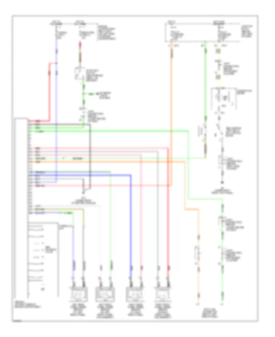
Anti-lock Brakes Wiring Diagram, Except Evolution for Mitsubishi Lancer Evolution RS 2006
List of elements for Anti-lock Brakes Wiring Diagram, Except Evolution for Mitsubishi Lancer Evolution RS 2006:
- Abs ecu (on right rear of engine compartment)
- Abs ind
- Abs solenoid valve
- Abs warning light relay (on junction block)
- C01
- C210
- C214
- Combination meter
- Cpu
- Data link connector (below left side of dash)
- Dedicated fuse 10 15a
- Engine compartment relay box (on left side of engine compartment)
- Exterior lights systems
- Fusible link 3 60a
- G14 (under front of center console)
- G3 (under right front kick panel)
- Hot at all times
- Hot in on
- Hot in on or start
- Hydraulic unit
- Joint connector 5 (behind instrument cluster)
- Joint connector 2 (behind instrument cluster)
- Joint connector 3 (behind right side of dash)
- Joint connector 6 (behind lower center of dash)
- Junction block (behind left end of dash)
- Left front wheel speed sensor (on left front wheel hub assembly)
- Left rear wheel speed sensor (at left rear wheel)
- Multi- purpose fuse 12 7.5a
- Multi- purpose fuse 2 7.5a
- Nca
- Pnk
- Red
- Right front wheel speed sensor (on right front wheel hub assembly)
- Right rear wheel speed sensor (at right rear wheel)
- Stoplight switch (above brake pedal, on bracket)