ENGINE PERFORMANCE
2.0L
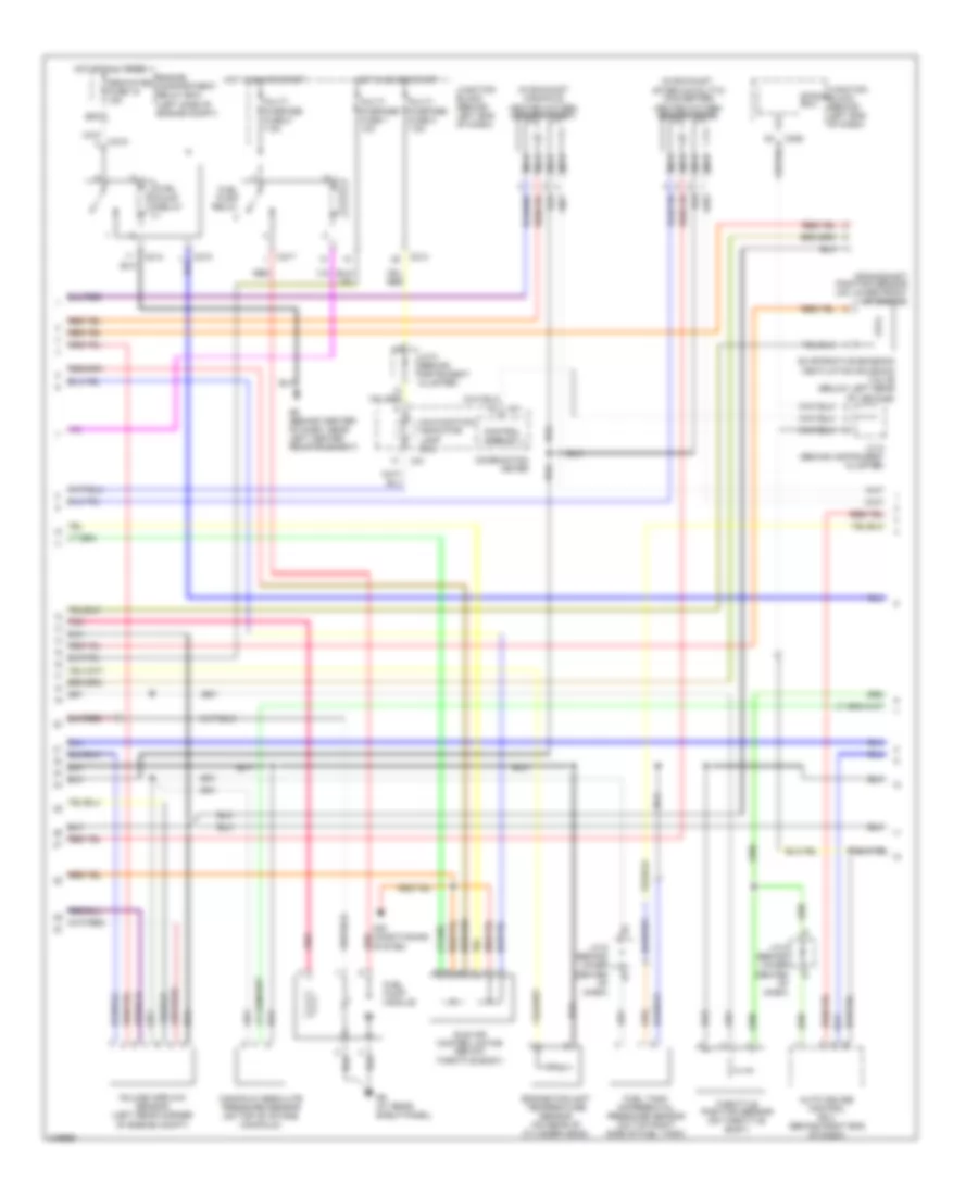
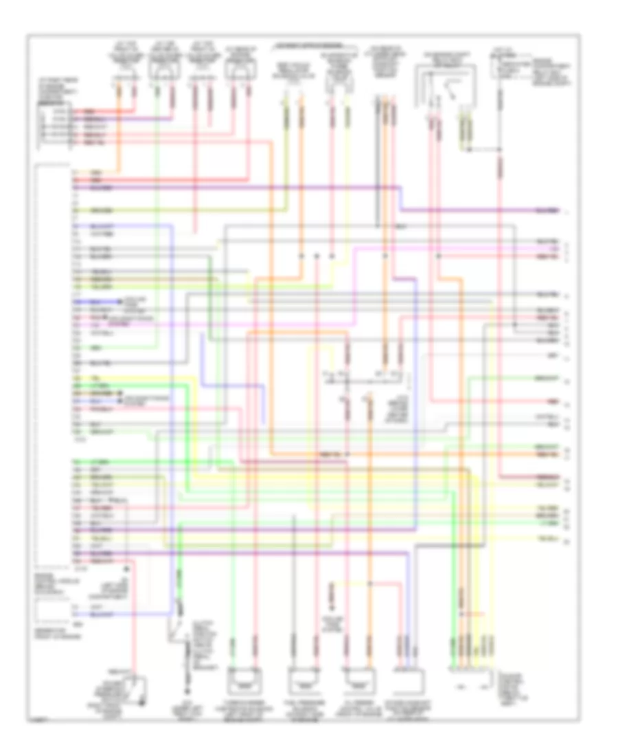
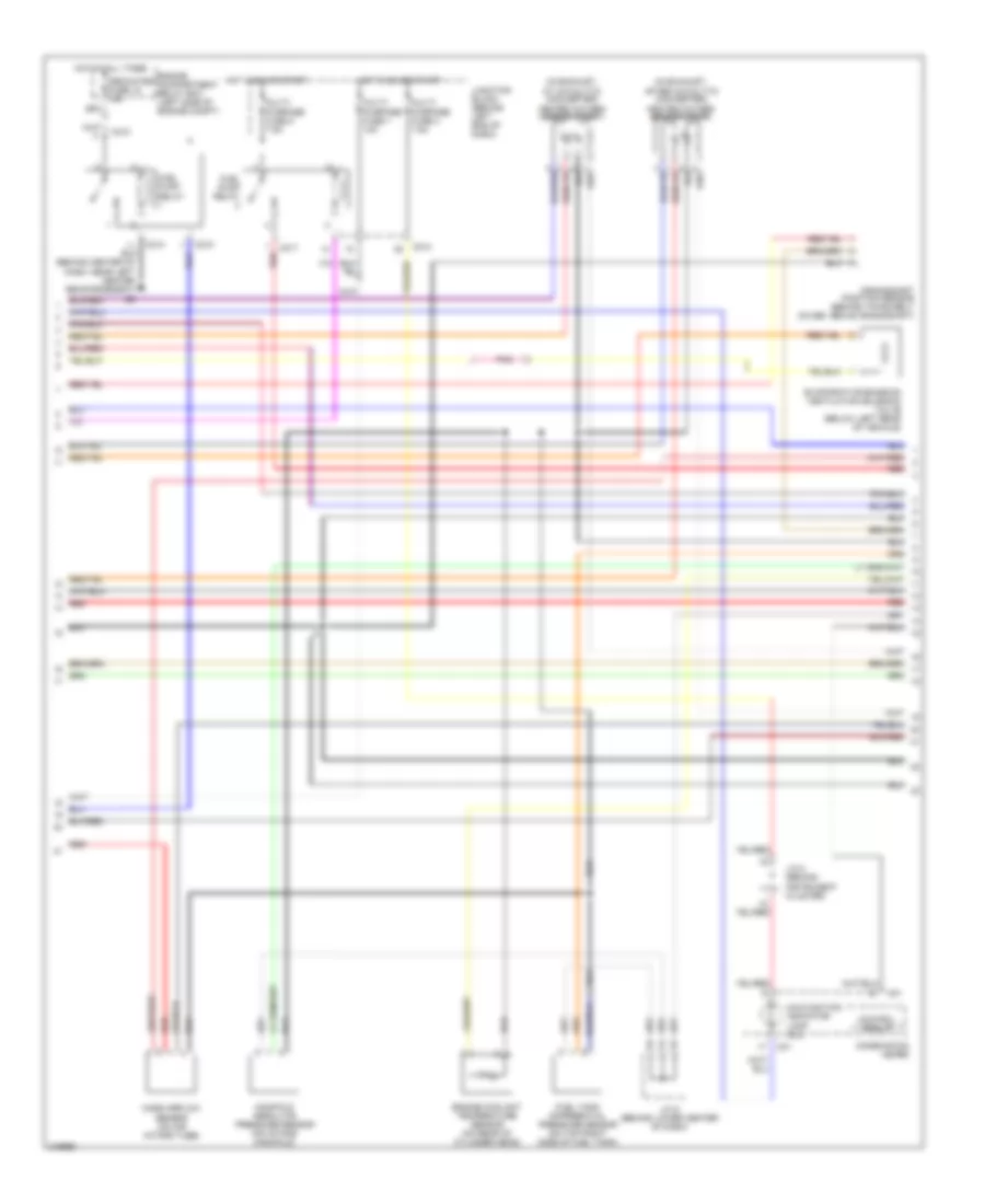
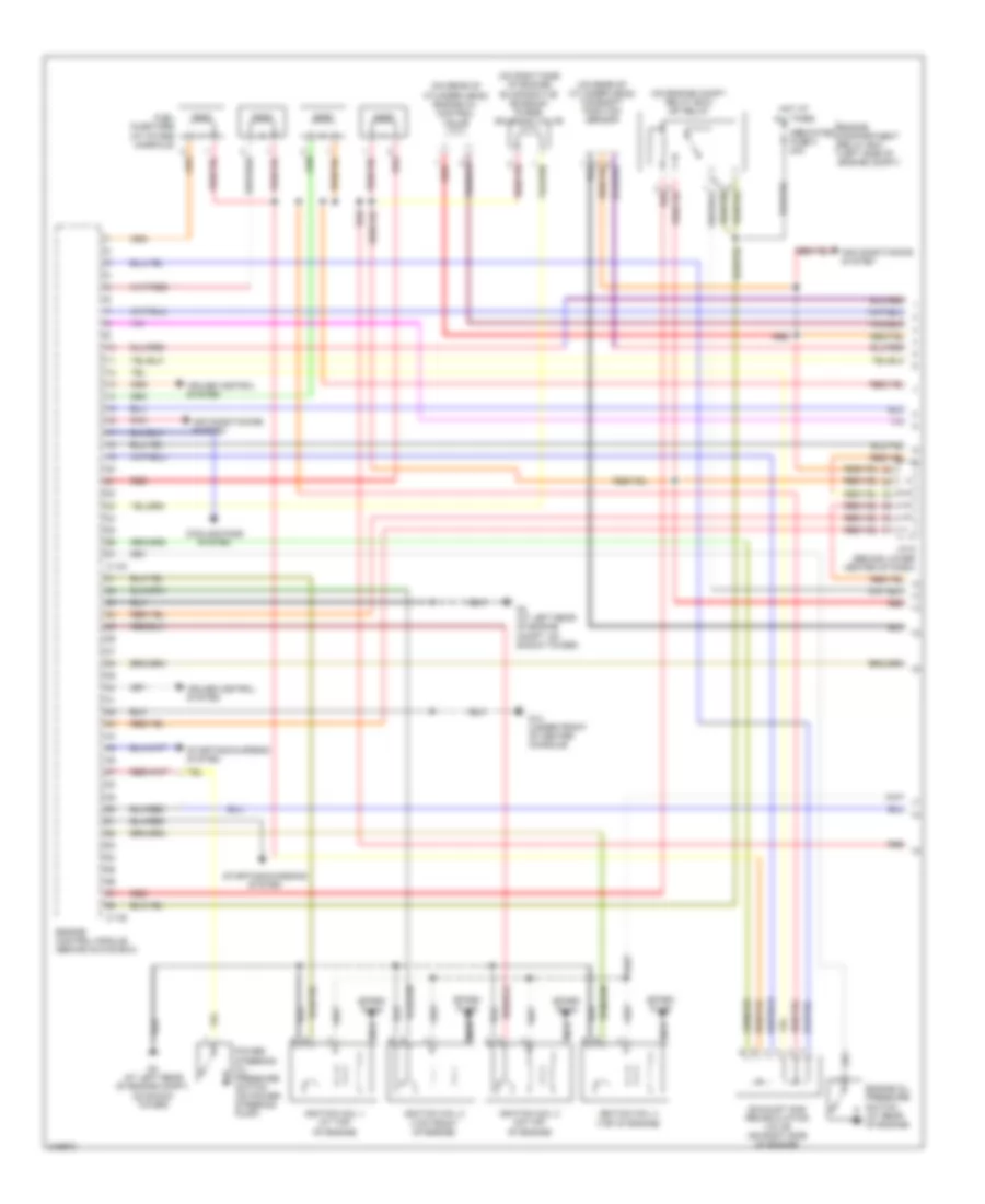
2.0L, Engine Performance Wiring Diagram, A/T (1 of 3) for Mitsubishi Lancer Evolution RS 2006

List of elements for 2.0L, Engine Performance Wiring Diagram, A/T (1 of 3) for Mitsubishi Lancer Evolution RS 2006:
- (behind lower center of dash) j/c 6
- (on engine compt relay box) mfi relay
- (on rear of cylinder head) camshaft position sensor
- (right side of engine)
- Air conditioning system
- C118
- C120
- Dedicated fuse 8 20a
- Egr solenoid valve
- Engine compartment relay box (left side of engine compt)
- Engine speed detection connector (in engine compt relay box)
- Evaporative emission purge solenoid valve
- G11 (left side of cylinder head, under throttle cable)
- G14 (under front of center console)
- G4 (at left rear of engine compt, on shock tower)
- Generator
- Hot at all times
- Ignition coil 1 (at top of valve cover)
- Ignition coil 2
- Instrument cluster system
- J/c 6 (behind lower center of dash)
- Nca
- Pnk
- Power steering oil pressure switch (right front of engine compt)
- Powertrain control module (behind glove box)
- Red
- Spark plugs
- Starting/ charging system
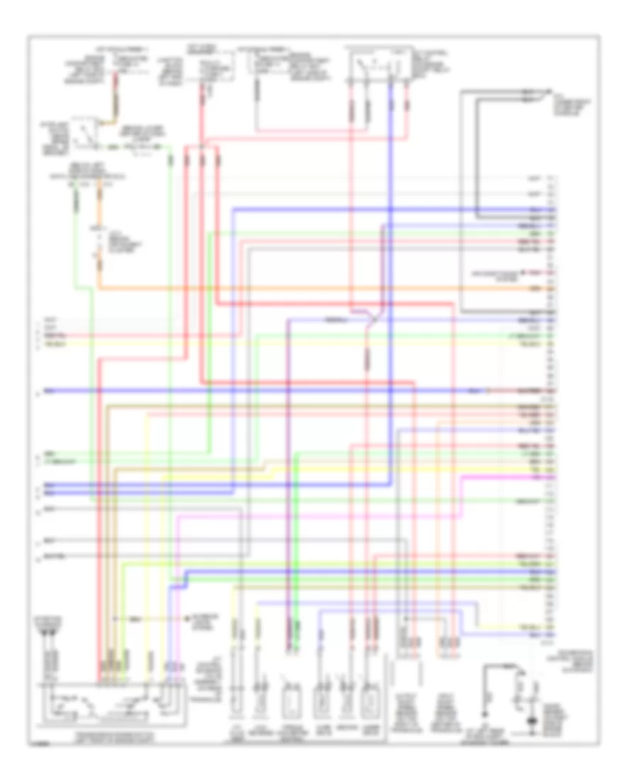
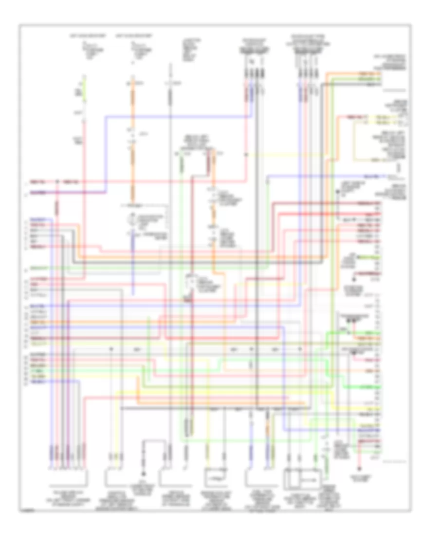
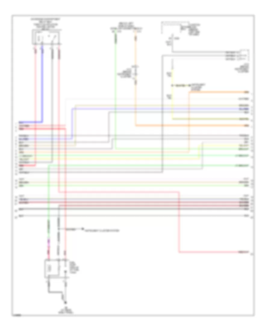
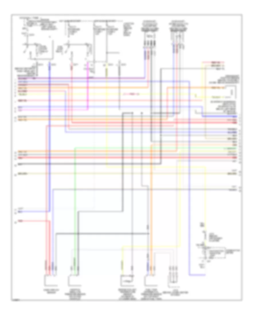
2.0L, Engine Performance Wiring Diagram, A/T (2 of 3) for Mitsubishi Lancer Evolution RS 2006
List of elements for 2.0L, Engine Performance Wiring Diagram, A/T (2 of 3) for Mitsubishi Lancer Evolution RS 2006:
- (in exhaust manifold) heated oxygen sensor (front)
- (in exhaust, after catalytic converter) heated oxygen sensor (rear)
- Air conditioning
- Auto cruise control ecu (behind right end of dash)
- C01
- C210
- C214
- C217
- C228
- Combination meter
- Control circuit
- Crankshaft position sensor (on lower front of engine)
- Dedicated fuse 15 15a
- Engine compartment relay box (left side of engine compt)
- Engine coolant temperature sensor (on rear of cylinder head)
- Etacs ecu
- Evaporative emission ventilation solenoid valve (below left rear of vehicle)
- Fuel pump module
- Fuel pump relay
- Fuel tank differential pressure sensor (on top right side of fuel tank)
- G6 (behind center of dash, near left center reinforcement)
- G9 (at rear shelf panel)
- Hot at all times
- Hot in on or start
- Idle air control motor (below throttle body)
- J/c 5 (behind instrument cluster)
- J/c 6 (behind lower center of dash)
- Junction block (behind left end of dash)
- Malfunction indicator lamp (mil)
- Manifold absolute pressure sensor (on top of intake manifold)
- Multi- purpose fuse 1 10a
- Multi- purpose fuse 2 7.5a
- Multi- purpose fuse 8 7.5a
- Nca
- Pnk
- Red
- System red
- Throttle position sensor (on throttle body)
- Volume airflow sensor (left rear corner of engine compt)
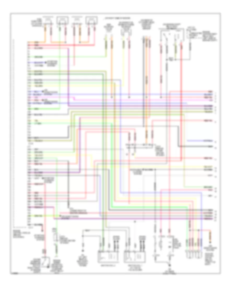
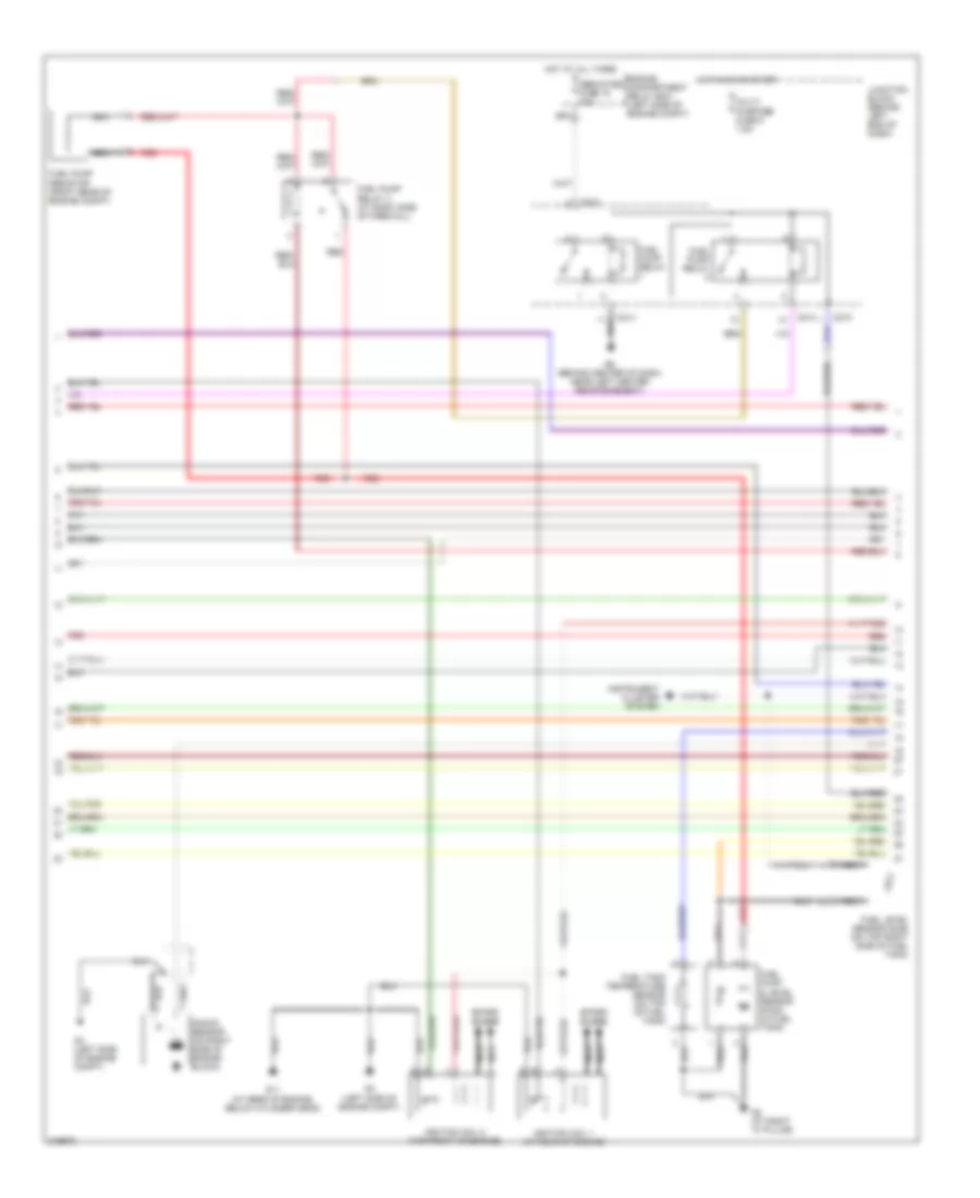
2.0L, Engine Performance Wiring Diagram, A/T (3 of 3) for Mitsubishi Lancer Evolution RS 2006
List of elements for 2.0L, Engine Performance Wiring Diagram, A/T (3 of 3) for Mitsubishi Lancer Evolution RS 2006:
- (behind lower center of dash) j/c 6
- (below left side of dash) data link connector (dlc)
- A/t control relay (on engine compt relay box)
- A/t control solenoid valve assembly (on rear of transaxle)
- A/t fluid temp
- Air conditioning system
- C114
- C116
- C14
- C15
- C210
- Dedicated fuse 10 15a
- Dedicated fuse 14 20a
- Engine compartment relay box (left side of engine compt)
- Engine compartment relay box (left side of engine compt) red
- Exterior lights system
- G14 (under front of center console)
- G4 (at left rear of eng compt, on shock tower)
- Hot at all times
- Hot in run or start
- Input shaft speed sensor (on top center of transaxle)
- J/c 2 (behind instrument cluster)
- Junction block (behind left end of dash)
- Knock sensor (on right side of engine block)
- Low/ reverse
- Multi- purpose fuse 3 7.5a
- Output shaft speed sensor (on top right of transaxle)
- Over drive
- Pnk
- Powertrain control module (behind glove box)
- Red
- Second
- Starting/ charging system
- Stoplight switch (above brake pedal, on bracket)
- Torque converter control
- Transmission range switch (left front of engine compt)
- Under drive
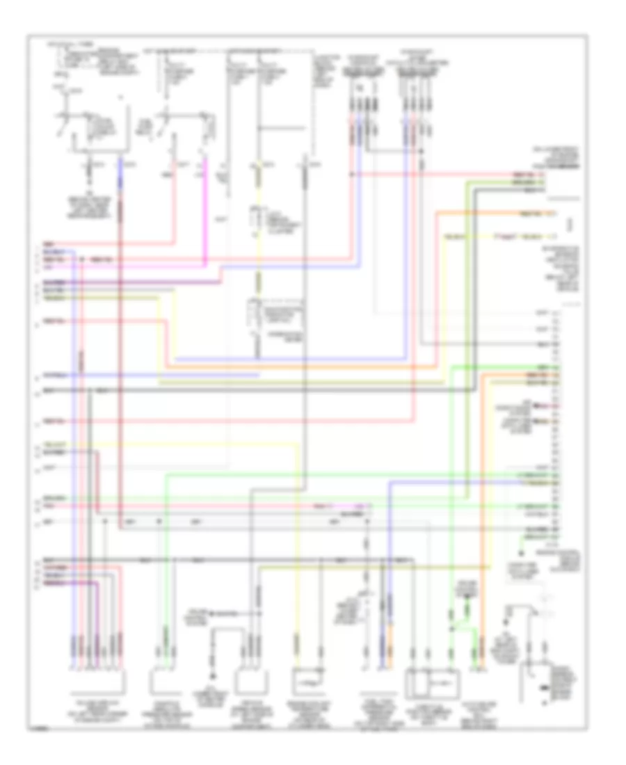
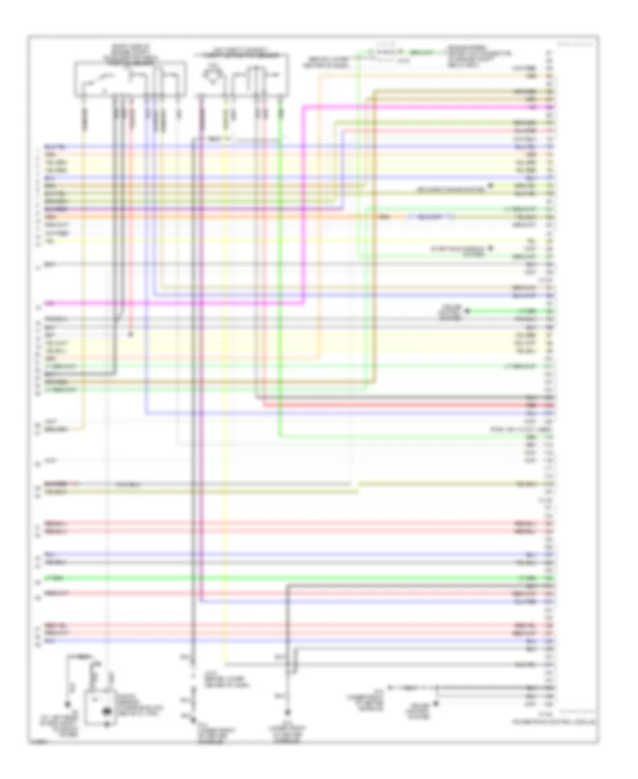
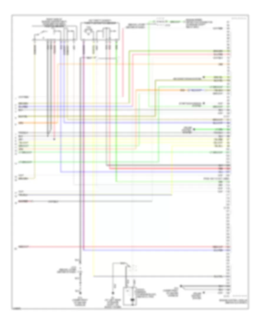
2.0L, Engine Performance Wiring Diagram, M/T (1 of 2) for Mitsubishi Lancer Evolution RS 2006
List of elements for 2.0L, Engine Performance Wiring Diagram, M/T (1 of 2) for Mitsubishi Lancer Evolution RS 2006:
- (on engine compt relay box) mfi relay
- (on rear of cylinder head) camshaft position sensor
- (on right side of engine)
- Air conditioning system
- Air conditioning system
- C117
- C119
- D10
- D12
- Dedicated fuse 8 20a
- Egr solenoid valve
- Engine compartment relay box (left side of engine compt)
- Engine control module (behind glove box)
- Engine speed detection connector (in engine compt relay box)
- Evaporative emission purge solenoid valve
- Fuel pump module (at fuel tank)
- G14 (under front of center console)
- G4 (at left rear of eng compt, on shock tower)
- G9 (at rear shelf panel)
- Hot at all times
- Idle air control motor (below throttle body)
- Ignition coil 1 (at top of valve cover)
- Ignition coil 2
- Instrument cluster system
- J/c 6 (behind lower center of dash)
- Nca
- Pnk
- Power steering pressure switch (right front of engine compt)
- Red
- Spark plugs
- Starting/ charging system
2.0L, Engine Performance Wiring Diagram, M/T (2 of 2) for Mitsubishi Lancer Evolution RS 2006
List of elements for 2.0L, Engine Performance Wiring Diagram, M/T (2 of 2) for Mitsubishi Lancer Evolution RS 2006:
- (in exhaust manifold) heated oxygen sensor (front)
- (in exhaust, after catalytic converter) heated oxygen sensor (rear)
- (on lower front of engine) crankshaft position sensor
- Air conditioning system
- Auto cruise control ecu (behind right end of dash)
- C115
- C210
- C214
- C217
- Combination meter
- Computer data lines system
- Cruise control system
- Dedicated fuse 15 15a
- Engine compartment relay box (left side of engine compt)
- Engine control module (behind glove box)
- Engine coolant temperature sensor (on rear of cylinder head)
- Evaporative emission ventilation solenoid valve (below left rear of vehicle)
- Fuel pump relay
- Fuel tank differential pressure sensor (on top right side of fuel tank)
- G14 (under front of center console)
- G4 (at left rear of eng compt, on shock tower)
- G6 (behind center of dash, near left center reinforcement)
- Hot at all times
- Hot in on or start
- J/c 5 (behind instrument cluster)
- J/c 6 (behind lower center of dash)
- Junction block (behind left end of dash)
- Knock sensor (on right side of engine block)
- Malfunction indicator lamp (mil)
- Manifold absolute pressure sensor (on top of intake manifold)
- Multi- purpose fuse 1 10a
- Multi- purpose fuse 2 7.5a
- Multi- purpose fuse 8 7.5a
- Nca
- Pnk
- Red
- Throttle position sensor (on throttle body)
- Vehicle speed sensor (at left side of engine compartment)
- Volume airflow sensor (on left rear corner of engine compt)
2.0L TURBO
2.0L Turbo, Engine Performance Wiring Diagram (1 of 3) for Mitsubishi Lancer Evolution RS 2006
List of elements for 2.0L Turbo, Engine Performance Wiring Diagram (1 of 3) for Mitsubishi Lancer Evolution RS 2006:
- (at rear of engine) injector
- (at right rear of engine compartment) injector resistor
- (at top center of valve cover) injector
- (at top front of valve cover) injector
- (on engine compt relay box) mfi relay
- (on rear of cylinder head) exhaust camshaft position sensor
- (on right side of engine)
- 47
- Air conditioning system
- B25
- C119
- C121
- Clutch pedal position switch (above nca
- Clutch pedal, on bracket)
- Control valve (front of engine)
- Cooling fans system
- Dedicated fuse 8 20a
- Egr vacuum regulator solenoid valve
- Engine compartment relay box (left side of engine compt)
- Engine control module (behind glove box)
- Evaporative emission purge solenoid valve
- Fuel pressure solenoid (on right side of engine)
- G15 (under left front kick panel)
- G4 (left side of engine compartment)
- Generator (front of engine)
- Hot at all times
- Idle air control motor (below throttle body)
- Intake camshaft position sensor (on rear of cylinder head)
- J/c 6 (behind lower center of dash)
- Nca
- Oil feeder
- Pnk
- Power steering pressure switch (right front of engine compt)
- Red
- Turbocharger wastegate solenoid (left front of engine compt)
2.0L Turbo, Engine Performance Wiring Diagram (2 of 3) for Mitsubishi Lancer Evolution RS 2006
List of elements for 2.0L Turbo, Engine Performance Wiring Diagram (2 of 3) for Mitsubishi Lancer Evolution RS 2006:
- C210
- C214
- Dedicated fuse 15 20a
- Engine compartment relay box (left side of engine compt)
- Fuel level sensor (sub) (on top right side of fuel tank)
- Fuel pump & level sensor (main) (in fuel tank)
- Fuel pump relay
- Fuel pump relay 3 (at right side of firewall)
- Fuel pump resistor (right rear of engine compt)
- Fuel tank temperature sensor (on top of fuel tank)
- G11 (at rear of engine, below cylinder head)
- G2 (at right "a" pillar)
- G4 (left side of engine compt)
- G6 (behind center of dash, near left center reinforcement)
- Hot at all times
- Hot in on or start
- Ignition coil 1 (at rear of engine)
- Ignition coil 2 (top front of engine)
- Instrument cluster system
- Junction block (behind left end of dash)
- Knock sensor (on right side of engine block)
- Multi- purpose fuse 8 7.5a
- Nca
- Red
- Spark plugs
2.0L Turbo, Engine Performance Wiring Diagram (3 of 3) for Mitsubishi Lancer Evolution RS 2006
List of elements for 2.0L Turbo, Engine Performance Wiring Diagram (3 of 3) for Mitsubishi Lancer Evolution RS 2006:
- c117
- (behind glove box) engine control module
- (behind instrument cluster) j/c 5
- (below left rear of vehicle) evaporative emission ventilation solenoid valve
- (below left side of dash) data link connector (dlc)
- (left side of of engine compt) g4
- (on exhaust manifold) heated oxygen sensor (front)
- (on exhaust pipe, downstream of catalytic converter) heated oxygen sensor (rear)
- (on lower front of engine) crankshaft position sensor
- Air condi- tioning system
- Air conditioning system
- Anti-theft system
- C01
- C119
- C14
- C15
- C210
- C214
- Combination meter
- Engine coolant temperature sensor (on rear of cylinder head)
- Engine speed detection connector (in engine compt relay box)
- Fuel tank differential pressure sensor (on top right side of fuel tank)
- G14 (under front of center console)
- Hot in on or start
- J/c 2 (behind instrument cluster)
- J/c 4
- J/c 5 (behind instrument cluster)
- J/c 6 (behind lower center of dash)
- Junction block (behind left end of dash)
- Malfunction indicator lamp (mil)
- Manifold absolute pressure sensor (at left rear of engine compartment)
- Multi- purpose fuse 1 10a
- Multi- purpose fuse 2 7.5a
- Nca
- Pnk
- Red
- Starting/ charging system
- Throttle position sensor (on throttle body)
- Transmissions system
- Vehicle speed sensor (on right side of transaxle)
- Volume airflow sensor (on left front corner of engine compt)
2.4L
2.4L, Engine Performance Wiring Diagram, A/T (1 of 5) for Mitsubishi Lancer Evolution RS 2006
List of elements for 2.4L, Engine Performance Wiring Diagram, A/T (1 of 5) for Mitsubishi Lancer Evolution RS 2006:
- (on engine compt relay box) mfi relay
- (on rear of cylinder head) camshaft position sensor
- (rear of cylinder head) engine oil control valve
- (right side of engine)
- (under front of center console) g14
- Air conditioning system
- C-134
- C-136
- Cooling fans system
- Cruise control system
- Dedicated fuse 8 20a
- Engine compartment relay box (left side of engine compt)
- Engine oil pressure switch (at rear of engine)
- Evaporative emission purge solenoid valve
- Exhaust gas recirculation valve (on right side of engine)
- Fuel injectors
- G4 (at left rear of eng compt, on shock tower)
- Hot at all times
- Ignition coil 1 (on top of engine)
- Ignition coil 2 (top front of engine)
- Ignition coil 3 (on top of engine)
- Ignition coil 4 (top of engine)
- J/c 6 (behind lower center of dash)
- Nca
- Pnk
- Power steering oil pressure switch (on power steering pump)
- Powertrain control module
- Red
- Spark plug
- Starting/charging system
2.4L, Engine Performance Wiring Diagram, A/T (2 of 5) for Mitsubishi Lancer Evolution RS 2006
List of elements for 2.4L, Engine Performance Wiring Diagram, A/T (2 of 5) for Mitsubishi Lancer Evolution RS 2006:
- (in exhaust, after catalytic converter) heated oxygen sensor (rear)
- (in exhaust, at catalytic converter) heated oxygen sensor (front)
- C01
- C210
- C214
- C217
- Combination meter
- Control circuit
- Crankshaft position sensor (behind timing belt cover, above crankshaft)
- Dedicated fuse 15 15a
- Engine compartment relay box (left side of engine compt)
- Engine coolant temperature sensor (on rear of cylinder head)
- Evaporative emission ventilation solenoid valve (below left rear of vehicle)
- Fuel pump relay
- Fuel tank differential pressure sensor (on top right side of fuel tank)
- Hot at all times
- Hot in on or start
- J/c 5 (behind instrument cluster)
- J/c 6 (behind lower center of dash)
- Junction block (behind left end of dash)
- Malfunction indicator lamp (mil)
- Manifold absolute pressure sensor (on intake manifold)
- Mass airflow sensor (on air intake tube)
- Multi- purpose fuse 1 10a
- Multi- purpose fuse 2 7.5a
- Multi- purpose fuse 8 7.5a
- Pnk
- Red
2.4L, Engine Performance Wiring Diagram, A/T (3 of 5) for Mitsubishi Lancer Evolution RS 2006
List of elements for 2.4L, Engine Performance Wiring Diagram, A/T (3 of 5) for Mitsubishi Lancer Evolution RS 2006:
- (below left side of dash) data link connector (dlc)
- (on engine compartment relay box)
- C14
- C228
- Etacs ecu
- Fuel pump module (at fuel tank)
- G9 (at rear shelf panel)
- Instrument cluster system
- J/c 2 (behind instrument cluster)
- J/c 5 (behind instrument cluster)
- Junction block (behind left end of dash)
- Pnk
- Red
- Throttle actuator control motor relay
2.4L, Engine Performance Wiring Diagram, A/T (4 of 5) for Mitsubishi Lancer Evolution RS 2006
List of elements for 2.4L, Engine Performance Wiring Diagram, A/T (4 of 5) for Mitsubishi Lancer Evolution RS 2006:
- A/t control relay (on engine compt relay box)
- A/t control solenoid valve assembly (on rear of transaxle)
- A/t fluid temp
- C210
- Dedicated fuse 10 15a
- Dedicated fuse 14 20a
- Engine compartment relay box (left side of engine compt)
- Engine compartment relay box (left side of engine compt) red
- Exterior lights system
- Hot at all times
- Hot in run or start
- Input shaft speed sensor (on top center transaxle)
- Interior lights system
- J/c 6 (behind lower center of dash)
- Junction block (behind left end of dash)
- Low/ reverse
- Multi- purpose fuse 3 7.5a
- Output shaft speed sensor (on top right of transaxle)
- Over drive
- Red
- Second
- Starting/ charging system
- Stoplight switch (above brake pedal, on bracket)
- Torque converter control
- Transmission range switch
- Under drive
2.4L, Engine Performance Wiring Diagram, A/T (5 of 5) for Mitsubishi Lancer Evolution RS 2006
List of elements for 2.4L, Engine Performance Wiring Diagram, A/T (5 of 5) for Mitsubishi Lancer Evolution RS 2006:
- (behind lower center of dash)
- (on throttle body) throttle position sensor
- (pins 109-112 not used)
- (right side of engine compt) accelerator pedal position sensor
- Air conditioning system
- C-138
- C-140
- C-142
- Cruise control system
- Engine speed detection connector (in engine compt relay box)
- G14 (under front of center console)
- G4 (at left rear of eng compt, on shock tower)
- J/c 6
- J/c 6 (behind lower center of dash)
- Knock sensor (in engine block, above oil pan)
- Powertrain control module
- Red
- Starting/charging system
- Tac motor
2.4L, Engine Performance Wiring Diagram, M/T (1 of 4) for Mitsubishi Lancer Evolution RS 2006
List of elements for 2.4L, Engine Performance Wiring Diagram, M/T (1 of 4) for Mitsubishi Lancer Evolution RS 2006:
- (on engine compt relay box) mfi relay
- (on rear of cylinder head) camshaft position sensor
- (on rear of cylinder head) engine oil control valve
- (on right side of engine)
- Air conditioning system
- C-133
- C-135
- Cooling fans system
- Cruise control system
- Dedicated fuse 8 20a
- Engine compartment relay box (left side of engine compt)
- Engine control module (behind glove box)
- Engine oil pressure switch (at rear of engine)
- Evaporative emission purge solenoid valve
- Exhaust gas recirculation valve (on right side of engine)
- Fuel injectors (at intake manifold)
- G14 (under front of center console)
- G4 (at left rear of engine compt, on shock tower)
- Hot at all times
- Ignition coil 1 (at top of engine)
- Ignition coil 2 (top front of engine)
- Ignition coil 3 (on top of engine)
- Ignition coil 4 (top of engine)
- J/c 6 (behind lower center of dash)
- Nca
- Pnk
- Power steering oil pressure switch (on power steering pump)
- Red
- Spark plug
- Starting/charging system
2.4L, Engine Performance Wiring Diagram, M/T (2 of 4) for Mitsubishi Lancer Evolution RS 2006
List of elements for 2.4L, Engine Performance Wiring Diagram, M/T (2 of 4) for Mitsubishi Lancer Evolution RS 2006:
- (in exhaust, after catalytic converter) heated oxygen sensor (rear)
- (in exhaust, at catalytic converter) heated oxygen sensor (front)
- C01
- C210
- C214
- C217
- Combination meter
- Crankshaft position sensor (behind timing belt cover, above crankshaft)
- Dedicated fuse 15 15a
- Engine compartment relay box (left side of engine compt)
- Engine coolant temperature sensor (on rear of cylinder head)
- Fuel pump relay
- Fuel tank differential pressure sensor (on top right side of fuel tank)
- Hot at all times
- Hot in on or start
- J/c 5 (behind instrument cluster)
- J/c 6 (behind lower center of dash)
- Junction block (behind left end of dash)
- Malfunction indicator lamp (mil)
- Manifold absolute pressure sensor (on intake manifold)
- Mass airflow sensor
- Multi- purpose fuse 1 10a
- Multi- purpose fuse 2 7.5a
- Multi- purpose fuse 8 7.5a
- Nca
- Pnk
- Red
2.4L, Engine Performance Wiring Diagram, M/T (3 of 4) for Mitsubishi Lancer Evolution RS 2006
List of elements for 2.4L, Engine Performance Wiring Diagram, M/T (3 of 4) for Mitsubishi Lancer Evolution RS 2006:
- (below left side of dash) data link connector (dlc)
- (on engine compartment relay box)
- C14
- C15
- D10
- D12
- Fuel pump module & fuel level sensor (at fuel tank)
- G14 (under front of center console)
- G9 (at rear shelf panel)
- Instrument cluster system
- J/c 2 (behind instrument cluster)
- J/c 5 (behind instrument cluster)
- Pnk
- Red
- Throttle actuator control motor relay
- Vehicle speed sensor (at left side of engine compt)
2.4L, Engine Performance Wiring Diagram, M/T (4 of 4) for Mitsubishi Lancer Evolution RS 2006
List of elements for 2.4L, Engine Performance Wiring Diagram, M/T (4 of 4) for Mitsubishi Lancer Evolution RS 2006:
- (behind lower center of dash)
- (on throttle body) throttle position sensor
- (pins 109-112 not used)
- (right side of engine compartment) accelerator pedal position sensor
- Air conditioning system
- C-137
- C-139
- C-141
- Cruise control system
- Engine control module (behind glove box)
- Engine speed detection connector (in engine compt relay box)
- G14 (under front
- G14 (under front of center console)
- G4 (at left rear of engine compt, on shock tower)
- J/c 6
- J/c 6 (behind lower center of dash)
- Knock sensor (in engine block, above oil pan)
- Of center console)
- Red
- Starting/charging system
- Tac motor