ANTI-LOCK BRAKES
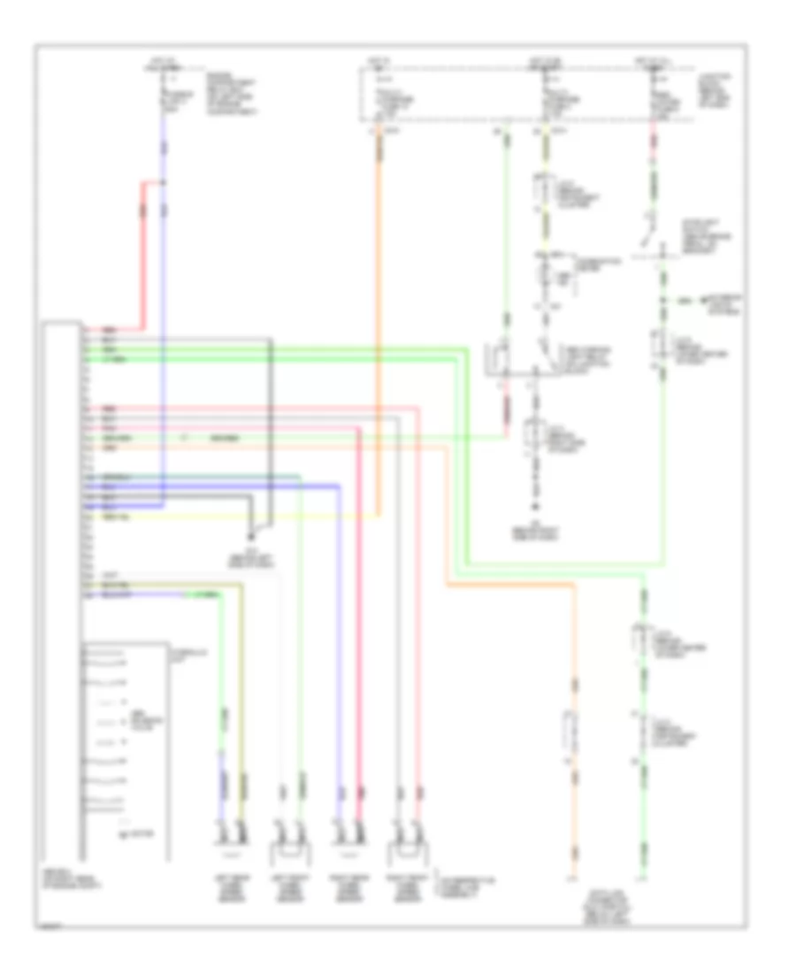
Anti-lock Brake Wiring Diagrams for Mitsubishi Lancer LS 2002
List of elements for Anti-lock Brake Wiring Diagrams for Mitsubishi Lancer LS 2002:
- (on respective wheel hub assembly)
- Abs ecu (on right rear of engine compt)
- Abs ind
- Abs solenoid valve
- Abs warning light relay (on junction block)
- C01
- C210
- C214
- Combination meter
- Data link connector (dlc) (partial) (below left side of dash)
- Ded- icated fuse 5 15a
- Engine compartment relay box (on left side of engine compartment)
- Exterior lights systems
- Fusible link 3 60a
- G14 (behind left side of dash)
- G3 (behind right side of dash)
- Hot at all times
- Hot in on
- Hot in on or start
- Hydraulic unit
- J/c 2 (behind instrument cluster)
- J/c 3 (behind right side of dash)
- J/c 5 (behind instrument cluster)
- J/c 6 (behind lower center of dash)
- Junction block (behind left end of dash)
- Left front wheel speed sensor
- Left rear wheel speed sensor
- Motor m
- Multi- purpose fuse 12 7.5a
- Multi- purpose fuse 2 7.5a
- Nca
- Pnk
- Red
- Right front wheel speed sensor
- Right rear wheel speed sensor
- Stoplight switch (above brake pedal, on bracket)
 English