ANTI-LOCK BRAKES
Anti-lock Brakes Wiring Diagram (1 of 2) for Nissan NV200 S 2014

List of elements for Anti-lock Brakes Wiring Diagram (1 of 2) for Nissan NV200 S 2014:
- (right rear of engine compt) e69
- 42a
- 43a
- 44a
- 45a
- 92a
- Abs actuator & electric unit (control unit) (right rear of engine compt)
- Abs/tcs/vdc control unit
- Actuator
- B29
- Bls
- Can-h
- Can-h yrs
- Can-l
- Can-l yrs
- Computer data lines system
- Dia k
- E43
- E69 (right rear of engine compt)
- Fl in
- Fl out
- Fr in
- Fr out
- Fuse & fusible link box (forward of battery)
- Fuse 10a
- Fuse block (j/b) (lower left end of dash)
- Fusible link i 40a
- Fusible link k 30a
- Hot at all times
- Hot in on or start
- Hsv 1
- Hsv 2
- Ign
- Interior lights system
- Ipdm e/r (intelligent power distribution module engine room) (left rear of engine compt)
- J/c e01 (center rear of engine compt)
- Left front wheel sensor (on left front wheel hub assembly)
- Left rear wheel sensor (on left rear wheel hub assembly)
- M gnd
- M12
- M57 (right kick panel)
- M69
- Motor
- Motor relay
- Pnk
- Red
- Relay unit
- Right front wheel sensor (on right front wheel hub assembly)
- Right rear wheel sensor (on right rear wheel hub assembly)
- Rl in
- Rl out
- Rr in
- Rr out
- S gnd
- Solenoid valve relay
- Stoplamp switch (top of brake pedal on bracket)
- Usv1
- Usv2
- Vdc off sw
- Vdc off switch
- Wp fl
- Wp fr
- Wp rl
- Wp rr
- Ws fl
- Ws fr
- Ws rl
- Ws rr
Anti-lock Brakes Wiring Diagram (2 of 2) for Nissan NV200 S 2014
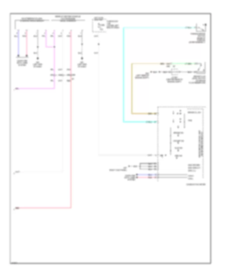
List of elements for Anti-lock Brakes Wiring Diagram (2 of 2) for Nissan NV200 S 2014:
- (on steering column) steering angle sensor
- (rear of center console) yaw rate/side/ decel g-sensor
- (w/ information display) unified meter control unit
- 34a
- 46a
- 48a
- 49a m69
- Abs ind
- Brake fluid level switch (on brake fluid reservoir)
- Brake ind
- Brake oil sw
- Can-h
- Can-l
- Combination meter
- Computer data lines system
- E24 (left rear of engine compt)
- E7 red
- Fuse 10a
- Fuse block (j/b) (lower left end of dash)
- Gnd (circuit)
- Gnd (ill)
- Gnd (power)
- Hot in on or start
- Ign
- J/c e01 (center rear of engine compt)
- M57 (right kick panel)
- M61 (left end of dash)
- M69
- Parking brake switch (base of parking lever assembly)
- Pkb
- Pnk
- Red
- Slip ind
- Vdc off ind