ANTI-LOCK BRAKES
Anti-lock Brakes Wiring Diagram for Suzuki Reno S 2005
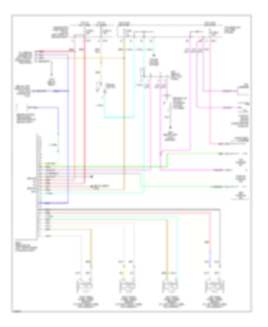
List of elements for Anti-lock Brakes Wiring Diagram for Suzuki Reno S 2005:
- (below ebcm) g106
- (below left side of dash) data link
- A13
- A14
- A19
- Abs
- Brake fluid switch (on brake master cylinder)
- Brake switch
- C102
- C107
- C201
- Connector (dlc)
- Cruise control system
- Drl module
- Ebcm (abs module) (left rear corner of engine compt)
- Engine control module (ecm) (center rear of engine compt)
- Engine room fuse & relay block (left front of engine compt)
- Fuse 10a
- Fuse 13 15a
- Fuse 2 60a
- Fuse 4 10a
- G106 (below ebcm)
- G204 (behind left audio bracket)
- Ground
- Hot at all times
- Hot in on or start
- I/p fuse block (left end of dash)
- Ign+
- Instrument cluster
- Left front wheel speed sensor (at left front wheel hub assembly)
- Left rear wheel speed sensor (at left rear wheel hub assembly)
- Oil feeding connector (left rear of engine compt, near ecbm)
- Parking
- Parking brake switch (under center console)
- Pnk
- Red
- Right front wheel speed sensor (at right front wheel hub assembly)
- Right rear wheel speed sensor (at right rear wheel hub assembly)
- S301 (behind left kick panel)
- Tcs
- Warning ind
 English