ANTI-LOCK BRAKES
Anti-lock Brakes Wiring Diagram for Suzuki Verona LX 2004
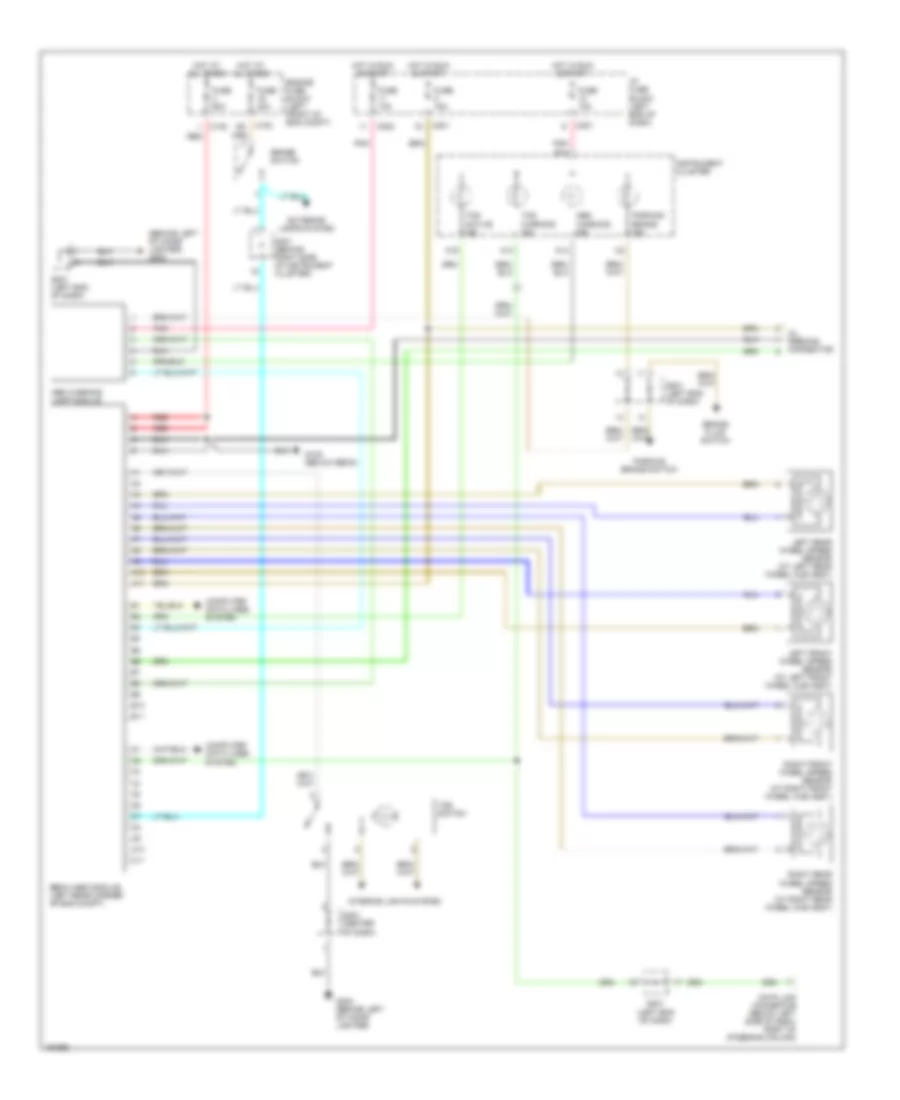
List of elements for Anti-lock Brakes Wiring Diagram for Suzuki Verona LX 2004:
- (behind left of cigar lighter) g202
- A10
- A11
- A13
- A14
- A16
- Abs warning ind
- Abs warning lamp module
- B10
- B11
- Brake fluid switch
- Brake switch
- C10
- C102
- C11
- C201
- C202
- Computer data lines system
- Data link connector (below left side of dash, right of steering column)
- Ebcm (abs module) (left rear corner of eng compt)
- Engine fuse block (left front of eng compt)
- Exterior lamps system
- Fuse 10a
- Fuse 15a
- Fuse 20a
- Fuse 60a
- G105 (below ebcm)
- G202 (behind left of cigar lighter)
- Hot at all times
- Hot in run & start
- I/p fuse block (left end of dash)
- Instrument cluster
- Interior lights system
- Left front wheel speed sensor (at left front wheel hub assy)
- Left rear wheel speed sensor (at left rear wheel hub assy)
- Oil feeding connector
- Parking brake ind
- Parking brake switch
- Pnk
- Pnk b14
- Red
- Right front wheel speed sensor (at right front wheel hub assy)
- Right rear wheel speed sensor (at right rear wheel hub assy)
- S201 (left end of dash)
- S203 (center of dash)
- S301 (behind right side of instrument cluster)
- Tcs active ind
- Tcs switch
- Tcs warning ind
 English