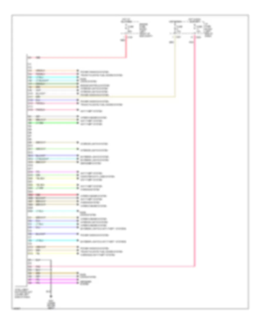
BODY CONTROL MODULES
Body Control Modules Wiring Diagram for Suzuki Verona LX 2004
List of elements for Body Control Modules Wiring Diagram for Suzuki Verona LX 2004:
- A10
- A11
- A12
- A13
- A14
- A15
- Anti-theft system
- B10
- B11
- B12
- B13
- B14
- B15
- B16
- B17
- B18
- B19
- B20
- B21
- B22
- B23
- B24
- B25
- B26
- B27
- B28
- B29
- B30
- C10
- C106
- C11
- C12
- C201
- C202
- Computer data lines system
- Defogger system
- Door locks system
- Engine controls system
- Engine fuse block (left front of eng compt)
- Exterior lights & anti-theft systems
- Exterior lights system
- Fuse 10a
- Fuse 60a
- G301 (under driver seat)
- Hot at all times
- Hot in run
- Hot in run & start
- I/p fuse block (left end of dash)
- Intelligent switching unit (lower left side of dash)
- Interior lights system
- Pnk
- Power windows system
- Red
- Trunk,tailgate, fuel doors system
- Warning & anti-theft system
- Warning system
- Wiper/washer system
 English