ANTI-THEFT
Forced Entry Wiring Diagram for Mazda 6 i 2003

List of elements for Forced Entry Wiring Diagram for Mazda 6 i 2003:
- 1996 vftc c
- 2.3l
- 3.0l
- Door lock control module (behind right side of dash)
- Flasher control module (behind left side of dash)
- G10
- G11 (under left front seat)
- G14 (center rear of trunk)
- G8 (behind left side of dash)
- Hazard warning switch
- Hood switch (at right front of engine compartment)
- Horn relay
- Horn system
- Hot at all times
- Hot in acc and run
- Instrument cluster
- Instrument cluster system
- Jb-01 p
- Jb-03 e
- Jb-05 e
- Jc-01 (left side of engine compartment)
- Jc-03 (behind right side of dash)
- Joint box (behind left kick panel)
- Key reminder switch (left side of dash)
- Left front door lock link switch/ left door key cylinder switch
- Left rear door lock link switch
- Left rear door switch
- Main fuse & relay box (on left front inner fender)
- Meter ig fuse 15a
- Powertrain control module (behind left side of dash)
- Right front door lock link switch
- Right rear door lock link switch
- Right rear door switch
- Room fuse 15a
- Security indicator
- Theft deterrent control module (under front of center console)
- Trunk compt light
- Trunk compt light switch (center rear of trunk)
- Trunk key cylinder switch
- Unlk
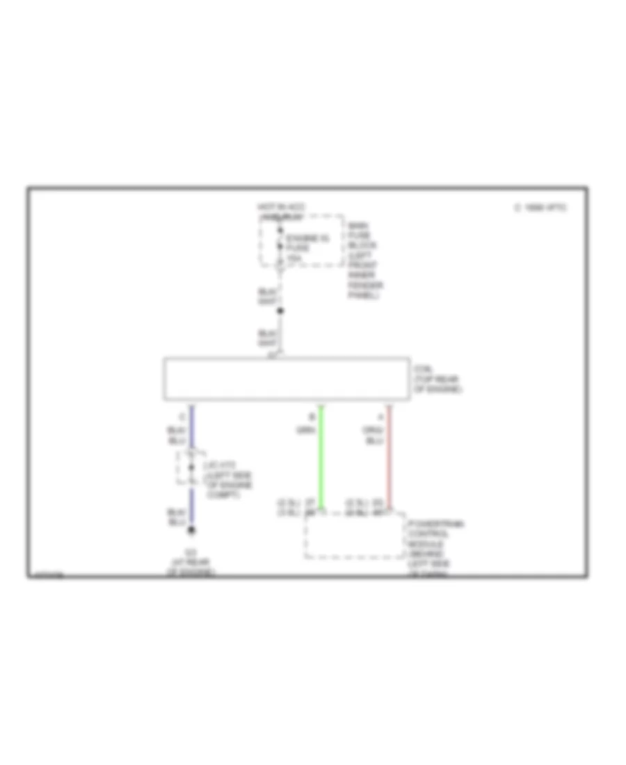
Immobilizer Wiring Diagram for Mazda 6 i 2003
List of elements for Immobilizer Wiring Diagram for Mazda 6 i 2003:
- (2.3l) (3.0l)
- 1996 vftc c
- Coil (top rear of engine)
- Engine ig fuse 15a
- G3 (at rear of engine)
- Hot in acc and run
- Jc-x13 (left side of engine compt)
- Main fuse block (left front inner fender panel)
- Powertrain control module (behind left side of dash)
 English