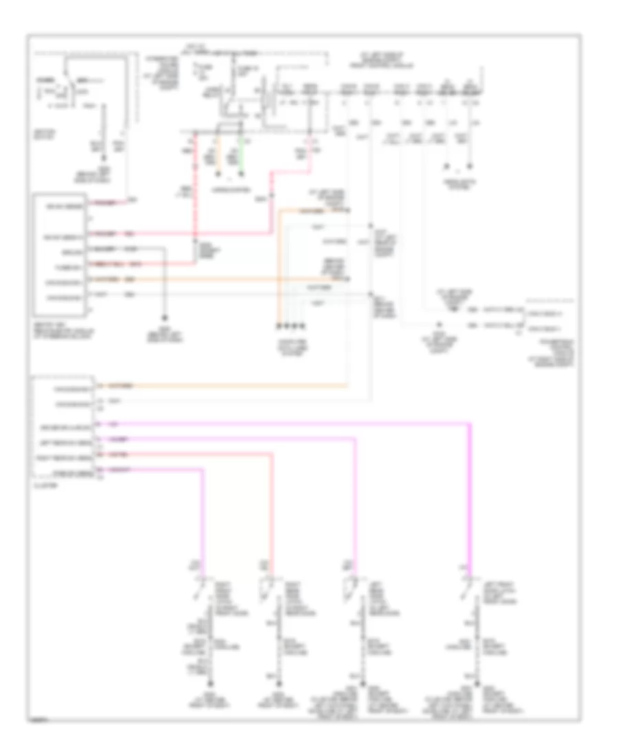
ANTI-THEFT
Anti-theft Wiring Diagram for Mitsubishi Raider SE 2007
List of elements for Anti-theft Wiring Diagram for Mitsubishi Raider SE 2007:
- (at left side of engine compt) front control module
- (at left side of engine compt) s101
- (at left side of engine compt) s105
- (behind center of dash) s212
- 87a
- A918
- Acc
- Can b bus b(+)
- Can b bus b(-)
- Can b bus(+)
- Can b bus(-)
- Can c bus (+)
- Can c bus (-)
- Can c bus(+)
- Can c bus(-)
- Cluster
- Computer data lines system
- D54
- D55
- D64
- D65
- Driver dr ajar sw
- F20
- Fuse 16 20a
- Fuse 20a
- Fused b(+)
- G20
- G200 (behind left side of dash)
- G300 (at center front of body)
- G300 (except highline) (at center front of body)
- G301 (highline) (club cab: behind left kick panel) (quad cab: at left front of body)
- Ground
- Headlights system
- Hi beam driver
- Horn relay
- Horns system
- Hot at all times
- Ign sw sens in
- Ign sw sense
- Ignition switch
- Integrated power module (at left side of engine compt)
- Ipm
- L33
- L34
- Left front door latch (in left front door)
- Left rear door latch (in left rear door)
- Left rear sw sens
- Lock
- Off
- Pass sw sens
- Powertrain control module (at right side of engine compt)
- Red
- Right front door latch (in right front door)
- Right rear door latch (in right rear door)
- Right rear sw sens
- Rly ctrl
- Run
- S100 (at left side of engine compt)
- S107 (at left rear of engine compt)
- S204
- S206 (except base)
- S211 (behind center of dash)
- S319 (except highline)
- S321 (highline)
- S324 (highline)
- Sens input
- Sentry key remote entry module (at steering column)
- Start
- Z109
 English