SUPPLEMENTAL RESTRAINTS
Supplemental Restraints Wiring Diagram for Mitsubishi Raider SE 2007
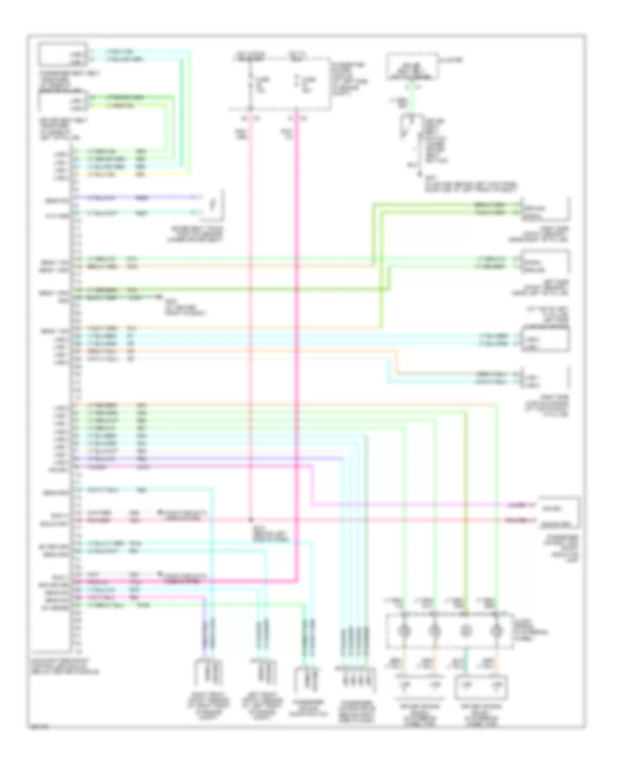
List of elements for Supplemental Restraints Wiring Diagram for Mitsubishi Raider SE 2007:
- (at top of left "a" pillar) left side curtain air bag
- Bus (+)
- Bus (-)
- Clock spring (in steering wheel)
- Cluster
- Computer data lines system
- D54
- D55
- Driver air bag squib 1 (in steering wheel pad)
- Driver air bag squib 2 (in steering wheel pad)
- Driver seat belt switch (under driver seat bottom)
- Driver seat belt switch sense
- Driver seat belt tensioner (at base of left "b" pillar)
- Driver seat track position sensor (under driver seat)
- F100
- F201
- Fuse 10a
- Fuse 20a
- G104
- G300 (at center front of body)
- G301 (club cab: behind left kick panel, quad cab: at left front of body)
- Gnd
- Ground
- Hot in run
- Hot in run or start
- Ind drv
- Indicator lamp
- Integrated power module (at left side of engine compt)
- Left front impact sensor (at left front of engine compt)
- Left side impact sensor 1 (near left "b" pillar)
- Line
- Line 1
- Line 2
- Occupant restraint controller module (below center console)
- Passenger air bag lamp on/off
- Passenger air bag on/off switch
- Passenger air bag squib (behind right side of dash)
- Passenger seat belt tensioner (at base of right"b" pillar)
- R104
- R106
- R13
- R14
- R15
- R16
- R261
- R263
- R42
- R43
- R44
- R45
- R53
- R54
- R55
- R56
- R61
- R62
- R63
- R64
- R79
- R80
- R81
- R82
- Return
- Right front impact sensor (at right front of engine compt)
- Right side curtain air bag (at top of right "a" pillar)
- Right side impact sensor 1 (near right "b" pillar)
- Run driver
- Run-start
- S210 (behind left side of dash)
- Sens 1 gnd
- Sens 1 sig
- Sens gnd
- Sens sig
- Sense
- Signal
- Sw return
- Sw sense
- Voltage
- Z104
 English