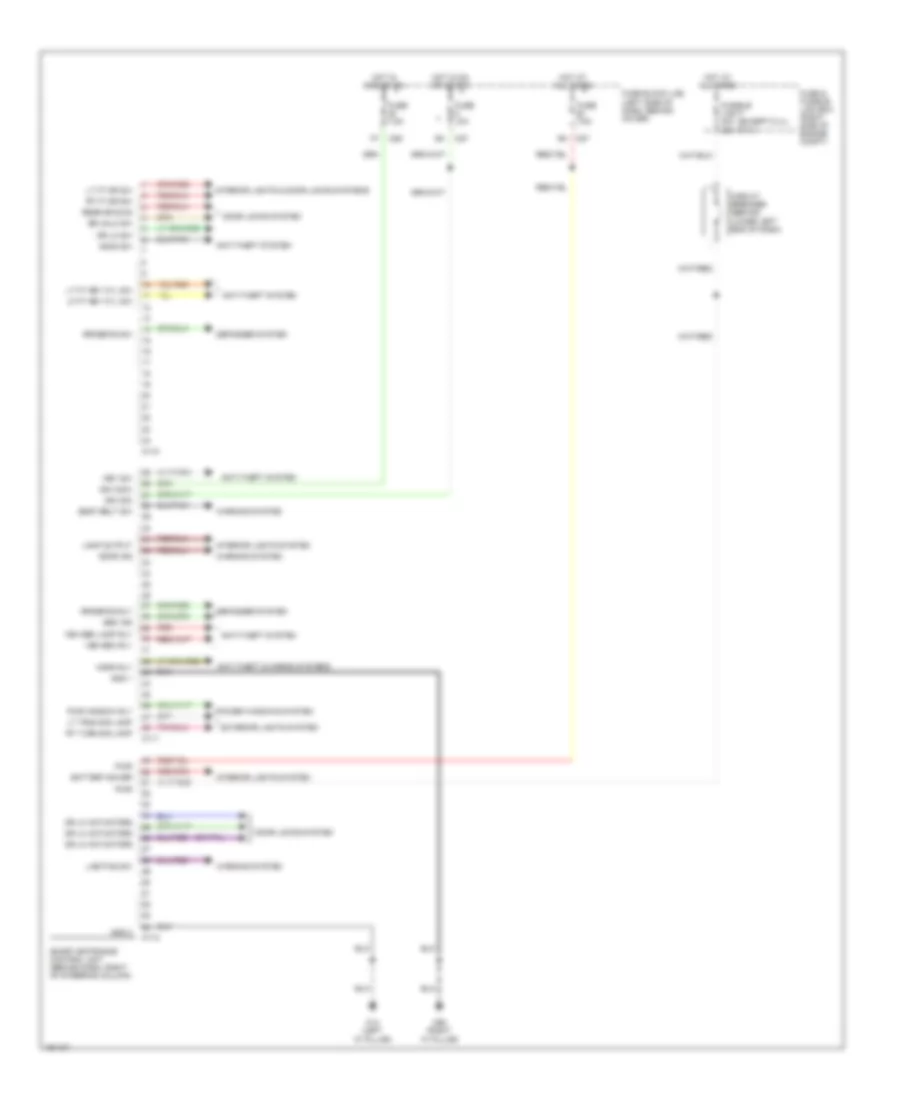
BODY CONTROL MODULES
Body Control Modules Wiring Diagram for Nissan Frontier 2004
List of elements for Body Control Modules Wiring Diagram for Nissan Frontier 2004:
- (except 2.4l) (2.4l)
- 30a
- Anti-theft & horns systems
- Anti-theft system
- Battery saver
- Circuit breaker (behind lower left end of dash)
- Defogger system
- Door ind
- Door locks system
- Dr lk actuators
- Dr lk sw
- Dr unlk sw
- Exterior lights system
- Fuse & fusible link box (right side of engine compt)
- Fuse 10a
- Fuse 7.5a
- Fuse block (j/b) (left side of dash, behind cover)
- Fusible link f 40a
- Gnd 1
- Gnd 2
- Hood sw
- Horn rly
- Hot at all times
- Hot in acc or on
- Hot in on or start
- Ign (acc)
- Ign (on)
- Interior lights & door locks systems
- Interior lights system
- Key sw
- Lamp output
- Lf ft key cyl sw
- Lighting sw
- Lt ft dr sw
- Lt ft key cyl sw
- Lt trun sig lamp
- M110
- M111
- M112
- M14 (left "a" pillar)
- M26
- M27
- M68 (right "a" pillar)
- Power windows system
- Pwr
- Pwr window rly
- Rear dr sws
- Red
- Rr defog rly
- Rr defog sw
- Rt ft dr sw
- Rt turn sig lamp
- Seat belt sw
- Sec ind
- Smart entrance control unit (behind dash, right of steering column)
- Veh sec lamp rly
- Veh sec rly
- Warning system
 English