COMPUTER DATA LINES
Computer Data Lines Wiring Diagram for Mitsubishi Outlander Sport ES 2014
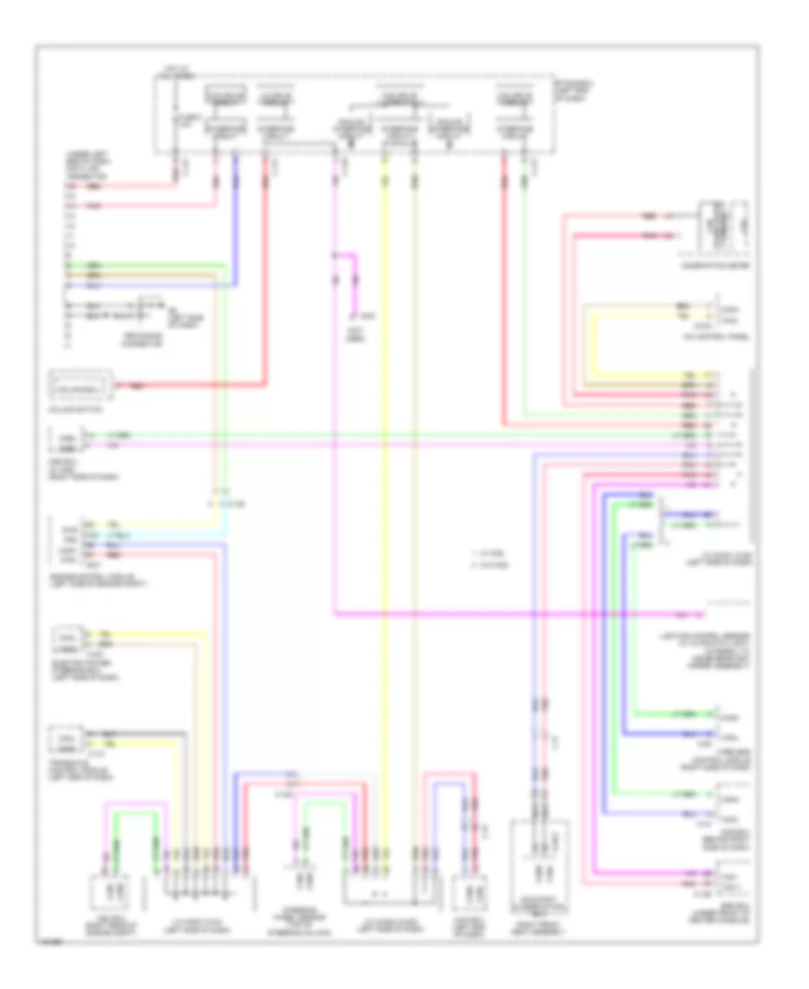
List of elements for Computer Data Lines Wiring Diagram for Mitsubishi Outlander Sport ES 2014:
- (not used)
- (under left end of dash) data link connector
- A/c control panel
- Analog interface circuit
- Asc ecu (right rear of engine compt)
- Awd ecu (left end of dash)
- B-27
- C-09
- C-10
- C-126
- C-128
- C-131
- C-17
- C-216
- C-221
- C-27
- C-411
- C-416
- C-417
- Can +
- Can -
- Can drive circuit
- Can transceiver circuit
- Canh
- Canl
- Cnbh
- Cnbl
- Column switch
- Column-ecu
- Combination meter
- Cpu
- D-48-2
- Diag
- E-02
- Electric power steering ecu (left side of dash)
- Engine control module (left side of engine compt)
- Etacs-ecu (left end of dash)
- Fmb
- Fuse 5 10a
- G6 (left side of dash)
- Grounding connector
- Hot at all times
- Interface circuit
- J/c (can1) (c-05) (left side of dash)
- J/c (can2) (c-202) (left side of dash)
- J/c (can3) (c-24) (left side of dash)
- Kos ecu (behind right side of dash)
- Lighting control sensor (w/ automatic light) (integral to inside rearview mirror assembly)
- Lin drive circuit
- Nca
- Occupant classification ecu
- Oss ecu (w/ k0s) (right side of dash)
- Pnk
- Red
- Right front seat assembly
- Srs ecu (under front of center console)
- Steering wheel sensor (top of steering column)
- Transaxle control module (left end of dash)
- W/ kos
- W/o kos
- Wireless control module (right side of dash)
 English